Continuing the (off) topic discussion from here:
http://www.candlepowerforums.com/vb/showthread.php?t=202598
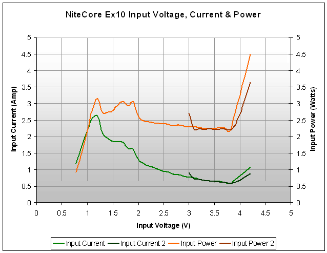
The question has been asked "What is the LED biased at?" and in pursuit of the answer, other things are revealed. I plotted the input voltage vs input current of a sample I have to determine some things about the circuit. The data is tabulated below (I will post a graph later after I upload the graphics)
Vin Iin
3.0 0.9
3.1 0.72
3.2 0.70
3.3 0.67
3.4 0.66
3.5 0.63
3.6 0.62
3.7 0.60
3.8 0.58
3.9 0.60
4.0 0.67
4.1 0.77
4.2 0.87
One thing you'll notice if you can visualize the data is that the current decreases and then increases. This tells you two things.
One is that the circuit is boost only. It is not designed for Li-Ion's as many incorrectly surmise (look at the runtime data and pictures of the light with RCR).
The statement is not conjecture, it is fact based on the data above. Having said that, it does work with RCR's for a number of reasons. At high current draw, RCR's experience enough sag that the lowered input voltage makes it appear the light is in regulation. If you were to have a low Vf LED, the light will actually run brighter initially until the cell voltage sags to the point where regulation kicks in. Above this point, the LED is in DIRECT DRIVE mode. Koala has data that shows this, and my data above also shows this.
OK, so what is the other thing this tells us? Well what's so nice about this graph is that it tells us the designed bias to the LED. How, why, where??? The plot of the data above shows an inflection point at about 3.8 volts. What's the big deal here? The current drawn from the supply at this point is the bias to the LED (on high is where I took my readings). So it appears that the LED was designed to be biased between 550mA and 600mA at the high setting. My measurements are not accurate at this point but I think it's close enough. I will take a more thorough reading later but for now, I think this answers a few burning questions about the EX10 and its circuit.
In all I'm impressed with the light. It is very high quality in many aspects and its price is difficult to beat. I have to say 4sevens and Nitecore has done a superb job in executing the design. And of course Don (McGizmo) gets credit for the PD concept that has now found its way into two commercial lights.
Cheers


