Piezo Switch Questions

GlazedDonut

Newly Enlightened
Joined
Sep 2, 2010
Messages
2
Working on my first DIY light. I't's a can-light with a modified mag-lite head and a single-mode LED module.

Bear with me here, because I'm a complete ignoramus with electrical stuff. I know enough to hook up a toggle switch with a boot, but from everything I've read, this option is the most prone to leakage. I'd also like to mount the switch to the light-head instead of the canister. It sounds like a Piezo switch is the way to go for maximum durability, so a couple of bonehead questions before I spend the money:

1. I may not be clear about how a Piezo switch works, but I'm understanding that it's pressure-actuated, which begs the question...why won't it become actuated with increasing water pressure as I descend?

2. I understand that a Piezo acts as a momentary contact switch, which needs additional "latching" circuitry to operate as an on/off toggle. I'm not smart enough to build something like that, but I found this product on another thread: http://www.pololu.com/catalog/product/750
If I replace the switch on this board with a Piezo, wouldn't this give me an on/off switch? If not, is it possible to find an on/off piezo switch, or a pre-fab circuit that a dummy like me can install a piezo switch to?
 
That polo circuit doesnt work in this application.

You can get a latching switch but it requires a constant 5v supply and they are very, very expensive and hard to find.

They work on a pressure differential so your slow descent underwater isnt quick enough to trigger it i believe.

Keep reading, as there is loads of goods threads here, welcome to CPF dive style!!
 
"pressure" doesn't cause piezo elements to produce voltage, movement does. That is, if you hit a piezo element and it bends quickly, the bending will produce voltage. However, the gradual increase in pressure from sea water is not enough to trigger a transistor.

I was actually thinking about making a piezo DIY switch, but only because they can stand many millions (at least) of repeated presses.
 
Piezo's are fine for underwater use; they are low profile, and bomb-proof. They will not turn on by themselves underwater... it is impossible to descend fast enough to actuate them. While underwater they work exactly like they were above water. They are momentary switches, so yes, you need to attach them to a latching circuit to make them press-on, press-off.

That said, Lucca recently posted a link to a manufacturer selling a piezo with inbuild latching circuitry.
http://www.apem.co.uk/pdf/PBA.pdf APEM ( with latch code : APEMPBA-R5-1-F-B-000 )

Looking at the specs I see the operating voltage range is 9-24V, which means if your battery is not within this range then it won't work. You would need a separate circuit to boost the voltage. And there are two current maximums mentioned, 200mA and 1A. Certainly if it's 200mA you would still need some sort of separate path/circuitry for the high power of the light, otherwise the piezo will be damaged. To my mind this is getting all 'too hard'. Lucca if you are reading this perhaps you clear this up for us?

I have experimented with the Polullu circuit and I have yet to make them work with the high power demands we typically use. I also found the Polullu person unhelpful (he simply didn't know) when asking for advice.

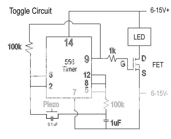
The alternative is use a normal piezo with a home-made latching circuit. The voltage range of these circuits are more 'torch friendly'. The one below is L 30mm; W 20mm; H 15mm, so about the same size as the piezo.

Why don't you give it a go yourself, with help from someone who knows components. It's a simple circuit. Parts sourced from electronics stores or online. Stick around this site long enough and you'll be giving us advice!
Toggle-circuit-RevisedLED.jpg

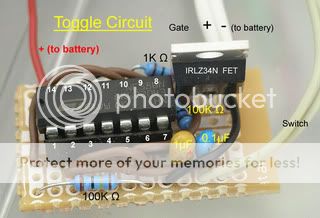
Photos, both sides...

ToggleCircuitPhotoA.jpg


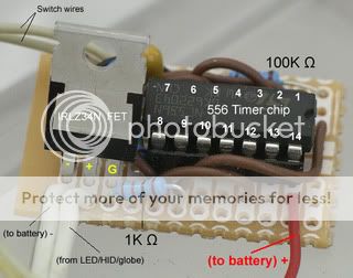
View from other side...
ToggleCircuitPhotoB.jpg
 
Last edited:
That 555 timer seems really excessive... I recommend an 8-pin microcontroller, plus a FET. A lot smaller and a lot smarter.
 
Wyager, always happy to hear of a simpler, cheaper solution.

Do you have a circuit in mind? By 'smarter' are you referring to something that needs programming by a computer or is it a ready-made chip?

If it's an off-the-shelf solution then I'll be the first in line, otherwise It'll be a case of weighing up the time/cost/effort of sourcing the software and parts and skillset to program the chip (I've never done this before).

Unsure what you mean by 'excessive', the 556 chip costs $1.00
 
Unsure what you mean by 'excessive', the 556 chip costs $1.00

It's large, it's power hungry, and it seems like a "dirty" method of getting this done. There are no pre-programmed micros for this task to my knowledge, but the benefits outweigh the marginal cost increases IMO. You have a much smaller chip with no external components needed, and it is able to perform much more complex tasks like sensing the amount of force applied to the piezo element (maybe a soft tap could be low mode) and it is able to intelligently change brightness levels by applying PWM to the FET.
 
Keep in mind, if under fair pressure the piezo element may reach the maximum and can no longer be actuated.

My personal choice for water applications is a magnetic switch with reed sensor or preferably a hall effect sensor.

if you stick with a piezo, just make sure that it takes more force to "floor it" than will be produced by the water during use.
 
if you stick with a piezo, just make sure that it takes more force to "floor it" than will be produced by the water during use.

What do you mean by "floor it"? If the disk is against a flat surface, chances are it won't even notice the water, it's the shock wave from your finger that creates the voltage. If the piezo was over an air gap or something, then the water might become a problem.
 
655...I have never had a problem, or even sensed a problem with actuating a piezo down to 50mts depth. That's good enough for me.

wyager, no argument from me, that you can program into chips things like modes, soft starts, and flashing warnings for battery life etc etc, all good stuff. Probably even chews less power. That's all well and good but it's no good to me (or Mr Donut) unless we know how to build it.

With the 556 circuit I can buy a few parts and solder them together in half an hour to make a piezo work as a toggle switch. As you say, quick and 'dirty'.

But for your more elegant, slightly more compact solution...What do I need to construct a circuit that does all these extra things, bearing in mind I don't already have the hardware/software and know-how? What costs are we talking about? What parts? Can you show us a circuit diagram?

I remember a few years back purchasing a small circuit called the Dive Genie. Its main feature was to slowly ramp-up an incandescent into overdrive without blowing. It looks like it's still being sold sold in project kit form here...
http://www.pcmus.com/Dive-Photos/Dive-Light-Genie.htm#Build
He also programs modes into, but jealously guards his intellectual property to the extent of sanding the part numbers off the FET and PIC chips. In doing so he is obviously trying to delay the dilution of his monopoly of this small market for DIY torches, but more importantly charges a higher price because of it (much higher than the 'quick and dirty' toggle circuit). That sort of behaviour to my mind seems to me to be a little paranoid and inconsistent with the spirit of dive torch blogs, but he views it differently, and I guess as a source of income he is entitled to.

Bottom line however, if this is what you are referring to...then how about starting a thread teaching us the basics, so we can all drag our torches into the 21st century.

I for one would be most grateful!
 
Last edited:
I've been looking at peizo switches and hope somone will be able to answer a question for me. The switch I'm looking at is from RS (the UK one), and for about £16 I can get a simple momentary action piezo. I want to use it with a maxflex (to drive 3 Seoul P4's), which seems to need a momentary switch. Anybody know if I can just link the piezo upto a maxflex without any additional components or power feeds, or is it not that simple? If it is simple, it will make construction so much easier, and should look really good too! I may even get an illuminated switch, and link it to the diagnostic LED output on the driver.

Is it that simple, or am I kidding myself?

Cheers,

Phil
 
Pressing the switch for longer than ½ a second but less than 1.5 seconds will select the nightlight
illumination level. This level is stored in the EEPROM as the current illumination level.
Pressing the switch for longer than 1.5 seconds will select the full brightness illumination level. This level
is stored in the EEPROM as the current illumination level.

As I see in manuals your driver uses different times for some functions so I assume that you have problems with piezo ( won't work PWM , just ON -OFF , maybe you get probloems too )
Get Hall or normal momentary switch. Reed have sometime problems with sticking contacts inside glass tube​
 
HTML:
im also very interested in using a programmable chip to use with the piezo ad did look into it a while ago, but it all seemed to complicated to set up for a couple of torches. especially when the 'quick and dirty' method works nicely and is fairly compact.

from what i remember you need the following

programmable chip
test board with interface to computer
software to program the chip
a moderate understanding of how to program

set up was roughly $50 ( i might be wrong here)

im sure there's a few other bits and bobs to know but i never actually tried getting all the parts together.

wyager . . care to enlighten some of us with how to go about it?

glazed donut . . . RS actually do the latching piezo made by APEM think it was £40 last time i looked.


safe diving

jon
 
It's large, it's power hungry, and it seems like a "dirty" method of getting this done. There are no pre-programmed micros for this task to my knowledge, but the benefits outweigh the marginal cost increases IMO. You have a much smaller chip with no external components needed, and it is able to perform much more complex tasks like sensing the amount of force applied to the piezo element (maybe a soft tap could be low mode) and it is able to intelligently change brightness levels by applying PWM to the FET

I see PWM usefull just in photo and video diving aplications . Or spare batteries.

In real diving you need one end only option switching tight beam - wide beam and light to max. Laws of nature keeps proper level of brightness in that way just right.
------------------------------------------------------------------------
For example: SST90 - aspherics give us tight spot:

purpose of beam is to penetrate water , to find obstacle/floor and there blow up beam which can light up all surroundings.

If I put there PWM on 60% I will not get enough light power to all surroundings , because beam it would not penetrate water and
''light intensity decreases with distance squared''

for close up neighborhood I like to light it up whole , but not too bright !
In that case you expand focus you spread concentrated beam in sphere ( here become inportant from lux ( surface planar ) to lumen (surface in sphere ))important and there illumination drops instantly (including distance in sphere ;its surface and volume by volume angle of illumination (steridians )and you have perfect light up neighborhood.
If you take there PWM what you get .... dark hole?


PWM is for YUPPIE's and internet divers.

BTW : I now uC
 
Last edited:
PWM is for YUPPIEs and internet divers.

afraid i cant completely agree with that.

iv often found the need for more then one light intensity, which pwm gives nicely.

most commonly during deco where im in mid water and need to see gauges, computers buddy etc, a low level light is required

also, something like a silted out wreck, i still want the tight beam but full power would cause too much back scatter, so a mid is very useful.

other then using separate lights for each there's not really a more efficient way, is there? :shrug:
moz-screenshot.png
 
Im surprised no one here has picked up the baton and started selling a little pcb that is a latching circuit for piezo's. It doesn't really matter how "down and dirty it is" We all want one, including me, and ill be happy to pay for it!!
 
Im surprised no one here has picked up the baton and started selling a little pcb that is a latching circuit for piezo's. It doesn't really matter how "down and dirty it is" We all want one, including me, and ill be happy to pay for it!!

Me 2 :)
 
wyager . . care to enlighten some of us with how to go about it?

I could probably post something later today, when I have more time. I'd be happy to draw up a diagram and some code.
 
Im surprised no one here has picked up the baton and started selling a little pcb that is a latching circuit for piezo's. It doesn't really matter how "down and dirty it is" We all want one, including me, and ill be happy to pay for it!!

ME TOO!!

Thanks for the input everyone. I did take a look at the latching piezo that was posted above, but looks like an $80 price-tag. For that much, I'll keep looking for a circuit. Simple-and-dirty is good enough for me, so I'll see if I can find someone that can help me out with the circuit that was posted above.

Thanks again.
 
Top