Poorman Mutli-Lux setup method

download

Flashlight Enthusiast
Joined
Jun 26, 2005
Messages
1,630
Location
Sol 3
Poorman Mutli-LED setup method

I found some interesting setup method to use the cheap driver board like 7135.
It can be used multi Seoul P7 or Cree,
like 2x li-ion to 2x LED or 3x li-ion to 3x LED.
It works quite well for me. Hope it helps you too.

The Cree XM-L have much lower Vin, 7135 does not work like 3x XM-L. (May-2012)

3xP7DriverSetupb.jpg

Each P7 can get 2.8A !!!
-----------------------------------------------------------------------------------------------------------

CreeMECDriverSetupb.jpg

Each LED get 1.4A !!!

Poormansetup3wire.jpg

3 wires only.

MC-Ewiring1-1.jpg


3xMCEdirect-drive.jpg
 
Last edited:

download

Flashlight Enthusiast
Joined
Jun 26, 2005
Messages
1,630
Location
Sol 3
Last edited:

Bimmerboy

Flashlight Enthusiast
Joined
Dec 30, 2004
Messages
2,072
Location
Long Island, NY
After reading those two threads, plus looking at the above diagrams, I'm still confused! :help:

Some questions:

Are you using a single 8 X 7135 board, or the controller/slave setup ?

How is it possible to put that much Vbatt into this? I thought the 7135 boards have a max input of 6V. Does your discovery mean it's 6V for each P7? If so, that's a pretty damn cool discovery.

In your first diagram, does the single P7 (connected to driver out) run in parallel or series with the other two P7's (connect to driver in)? I'm assuming series, because Vin would match the total emitter Vf, but I'm not understanding the diagram. EDIT: Think I figured it out... they'd be in series because driver in to driver out is in series. Correct?

Hoping to understand this setup, because it could be EXACTLY what I need to regulate 3 or 4 X P7 with 4 X Emoli.

Thanks, Download!
 
Last edited:

download

Flashlight Enthusiast
Joined
Jun 26, 2005
Messages
1,630
Location
Sol 3
Bimmerboy,
I would suggest you try single 7135x4 board first, ( just half of current go though the LED ) muti-level or not, my setting is same as NetKidz & StefanFS wiring method 2.8A.

If you use 4 X Emoli, your driver connect 1x P7 and 3x P7 serial outside will be fine. ( 1 li-ion serve 1 LED only )

I tried & run for a while. It works quite OK for me.
eg: 3x P7 - The driver handle 1x li-ion power only, the serial P7 x2 share the 2x li-ion voltage, and all LED react the same function of the driving LED.

Hope this helps. :)
 

Bimmerboy

Flashlight Enthusiast
Joined
Dec 30, 2004
Messages
2,072
Location
Long Island, NY
I think I'm beginning to see the light. :)

The extra P7's connected to the "driver in" side are providing the voltage drop so that the board itself only sees the Vbatt of one Li-ion. Do I have that correct?

If so, that means you can't use 4 X Li-ion for three P7's in an attempt to get full regulation throughout the entire runtime, but that cloud has a silver lining anyway, since you'd never know when the batteries are getting too drained. The light wouldn't dim until the batteries were being damaged. So, there's sort of a built-in protection here with a 1:1 setup... our eyes. ;)

I definitely vote for this as "killer find of the month", maybe the year! A cheap, multiple P7 driver that seems to be working well. Totally surprised there's been no reaction to this.

Thanks again, Download. This sounds excellent! :thumbsup:

P.S. The heck with half current... I'm going straight for 2.8A! :party: I'm also thinking of using a D2DIM with this.
 
Last edited:

Doh!Nut

Newly Enlightened
Joined
Nov 6, 2006
Messages
166
Location
West London
I am glad I found this, I was just about to post a question on the similar circuit, I had a look at the data sheet http://www.micro-bridge.com/data/ADD/AMC7135.pdf and saw that unlike most drivers that have four connections and the LEDout is not the same as the Batt Neg.

The AMC7135 has only three connections, with a common ground so whatever goes through the LED comes out the ground (and straight into the next LED :twothumbs)

This means that I could have a 3 P7 light running from 12v NiMh pack

Nick
 

download

Flashlight Enthusiast
Joined
Jun 26, 2005
Messages
1,630
Location
Sol 3
Bimmerboy, You do see it, 4x P7 is very bright light.
D2DIM should work better for direct drive, only need more trick to wire extra control switch.
This wiring method is just easier only.

Nick, in my test result, the multi-level driver did not survive to drive more the 3x Ni-MH per LED in 3 x LED setting. (I took out all diode to gain more voltage)
I would suggest 3 P7 run 9 Ni-MH Max. only.

Cheers! :wave:
 
Last edited:

jeffosborne

Enlightened
Joined
May 15, 2007
Messages
252
Location
southern Indiana
From the AMC7135 data sheet:

Supply voltage range 2.7V ~ 6V

You are putting 10.8 volts nominal on a device that likes only up to 6 volts.

Have you TRIED the circuit you are proposing?
Anybody read the data sheets?

Warm regards,
Jeff O.


download

Flashlight Enthusiast
Joined
Jun 26, 2005
Messages
1,630
Location
Sol 3
Both of wiring method I am using right now.
It works fine for me. Just share this little finding.
 

Doh!Nut

Newly Enlightened
Joined
Nov 6, 2006
Messages
166
Location
West London
I am a little surprised that did not work with 4 NiMh per LED, but was half thinking about the circuit I was considering where the output of one driver went to the Vin (or Vdd) of the next stacked driver. That would be within the voltage specs but would be wasting lots of power.


The worst case for downloads circuit above is that you have low Vf LED, say 3.2V

So a fresh 12v Pack gives 14+v
14v minus two times 3.2v gives 8.1v accross the driver - way off spec. You would have to drop two or three cells to bring it back down to spec. (as download said)

Four P7 (Gulp:devil:)

14.5v - (3*3.2v) = 4.9 accross driver (worst case)
Running condition
12.5 - (3 * 3.7v) = 1.4v accross driver and LED- ie it wont work :confused:.
Even if the driver did not drop any voltage accross itself and the voltage was devided equally that would leave 3.1v accross each LED, not enough for 350ma.

If I want to use this in a torch with existing 12v NiMh pack maybe I will have to get a circuit, and find the actual vf of the 3 P7s and put in a small resistor.

N
 

download

Flashlight Enthusiast
Joined
Jun 26, 2005
Messages
1,630
Location
Sol 3
I mean the multi-level circuit IC will not survive, not AMC7135, 7135 just overheat, cutdown the power & flash. It will not die easily.

You may try this:

(P7 + 7135 with multi-level) Serial (P7 + 7135) Serial (P7 + 7135) -> 12V

Each 7135 board have diode to drop the voltage a little, should work now.
 

OldNick

Newly Enlightened
Joined
Sep 3, 2006
Messages
130
Location
Western Australia
Download

This is very clever. I believe you have tried this and it works, but I am completely puzzled. :huh:

Simple circuit, but I don't get the principles. What does that board do that allows you to connect the Bat (+) to the two lower LEDs (-) that are not driven by the board (the "slaves")? It's effectively in series with the battery and boosting the volts? Or is it sharing the volts between the driver/LEd combo and the slave LEDs?

Why do the lower ("slave") LEDs follow the current of the two that are actually driven?

Also, if you used a single board instead of the parallel version, I assume you could use the board to drive, say, just 2 Crees "in series" and not the paralleled version you have.

Given that I actually do not want to drive my Crees at 1400mA, how do you use this? Do you have a multi-stage board, and not use high, or do I use one of the lower-current boards (which I think have only 3 of the ICs on them rather than 4)

I would appreciate any help from you (or anyone) about this.

Nick (the second)
 
Last edited:

Mr Happy

Flashlight Enthusiast
Joined
Nov 21, 2007
Messages
5,390
Location
Southern California
This is very clever. I believe you have tried this and it works, but I am completely puzzled.

...

I would appreciate any help from you (or anyone) about this.
I did not see this thread earlier, but it looks like a very creative use of the driver.

It works because the 7135 is a linear current regulator (in other words it is like a fancy variable resistor in the circuit). Because it is a linear regulator, the current everywhere in the circuit is the same, just as if it were a simple resistor.

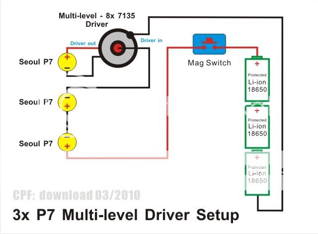
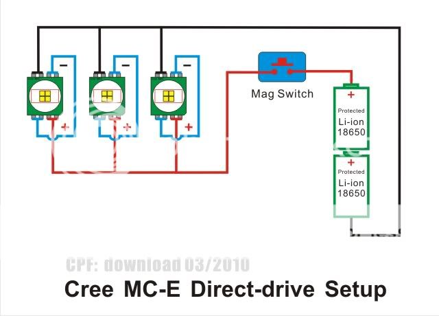
In the first circuit then, all three P7's see whatever current the 7135 is set to, for example 2.8 A.

Now let's look at the voltages. When fully charged, three Li-ions in series produce about 12 V. On the supply side of the 7135 we have two P7's in series. Each of these will drop their Vf, which for the sake of example we might assume to be 3.5 V. Therefore the voltage seen on the input side of the 7135 will be 12 - 2 x 3.5 = 5 V. We therefore are within the allowable input range of not more than 6.0 V. Lastly, the 5 V input provides enough margin to drive the P7 on the output, assuming the same Vf of 3.5 V.

Out of curiosity, we can take the worst case when the battery is discharged and the P7's happen to have a higher Vf of 3.7 V. Close to discharge the battery will have a voltage nearer to 9 V than 12 V. From this we subtract 2 x 3.7 V giving 1.6 V. Clearly 1.6 V on the input to the 7135 is nowhere near enough to drive the output LED, so all the P7's will have shut off long before the battery gets this low.

As a result, the setup will not be able to extract all the charge from the battery, but on the good side it will protect against over discharge and prolong the life of the cells.

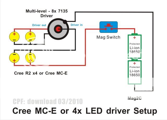
The second circuit can be analyzed in a similar way, except that now two LED's have been put in parallel. The trouble here is that if the two LED's have different Vf values, the current will not be equally distributed between them. Worse, if one gets hotter than the other the imbalance will tip further in the unequal direction.

It is not typically advised to put LED's in parallel because of this problem of current balancing. It may work but it's not a robust arrangement.
 
Last edited:

download

Flashlight Enthusiast
Joined
Jun 26, 2005
Messages
1,630
Location
Sol 3
Hi OldNick,

I updated the diagrams for protected 18650 li-ion only, this is exactly what I am actually using.

The 7135 board transfer the extra voltage to heat before feeding LED. (like 4x 7135 ~1.2A to LED)

Because the Voltage of my Li-ion and LED Vin is close. So the extra voltage of multi-Li-ion is still OK for 7135. But not much.
If you get ultra low voltage of LED, result may be different.

In actual finding, 3x P7 diagram, the (two lower LEDs) share most the voltage of 2x li-ion, the driver take care 1x li-ion with little extra, when the muli-level driver switch dim, it limited the current of whole circuit, so all the led dim as same level.

In 4 lux diagram, mainly use 2x Li-ion, it need 2x LED in serial to share it.
Parallel extra LED are just share the current of 8x 7135, not a must in 3x 7135.
If you use 2x LED only, wire LED like diagram, (no more extra parallel LED) one of the LED use (3x 7135) for 2x Li-ion is fine. Each LED got ~0.9A.


Mr Happy,
You said better than me. :thumbsup:
In the real world, when the battery voltage lower than LED, driver run as direct driver and LED will run lower Vf too. It will drain all the battery dry till protected circuit works.

Hope this helps! :)
 

OldNick

Newly Enlightened
Joined
Sep 3, 2006
Messages
130
Location
Western Australia
Ok. Thanks for the replies from both of you. My brain needed a kick.

I am OK with electrics, but just coming up to speed on these sort of current regulators, as distinct from voltage regulators.

I get the shared current. The 7135s actually allow a current by raising and lowering voltage then. As you say, a smart resistor. So as long as the volts left over from the "free" LEDs is within the volts of the 7135s, all stages will work. Within that range, the 7135s share the voltage across the circuit to maintain the current.

But for all of me, the two "free" P7 LEDs (and the free ones in the Cree cct) are in reverse polarity. The Positive of the battery goes to the Negative side of the LEDs.

Sorry if I am missing something (apart from the functioning grey matter)

Nick
 

Mr Happy

Flashlight Enthusiast
Joined
Nov 21, 2007
Messages
5,390
Location
Southern California
But for all of me, the two "free" P7 LEDs (and the free ones in the Cree cct) are in reverse polarity. The Positive of the battery goes to the Negative side of the LEDs.
I think you are right. I noticed that too, but I didn't want to make my post any longer than it already was.

The positive (anode) side of the LED should be facing the positive (+) terminal of the battery. The LEDs do all appear to be backwards in the diagrams. The red and black coloring of the wires seems a bit out of place too...
 

OldNick

Newly Enlightened
Joined
Sep 3, 2006
Messages
130
Location
Western Australia
Oh good...for me anyway.

I reckon the LED that is actually driven by the board is OK for polarity. It's just that the connection to the centre + of the board is "blocked" by the board. It's difficult to draw that bit without either what we see or having the LED connected to both centre and edge, or look that way.

Download : Care to clear this up? As far as I am concerned, the idea is brilliant whether you have got it wrong in the drawing or not, and if the drawing is correct, then I need help to understand.

Nick
 

Latest posts

Top