You are using an out of date browser. It may not display this or other websites correctly.
You should upgrade or use an alternative browser.
You should upgrade or use an alternative browser.
Poorman Mutli-Lux setup method
- Thread starter download
- Start date
 Help Support Candle Power Flashlight Forum
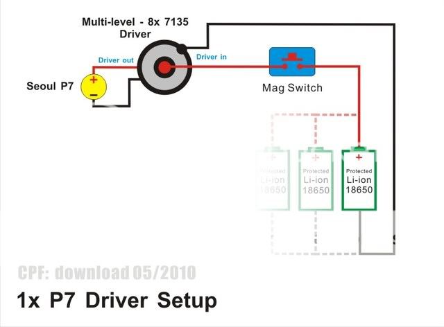
Here is the 1xP7 setting. 1x Driver to 1x LED with 1 battery (or parallel more), Max.2.8A to LED.
Parallel more battery will extend the run-time.

I am planning to build my first LED with two parallel 18650(s) and this is exactly the way I was planning to do that. Can somebody tell me if there are some negative sides of parallel connection? In my (non-expert) view this design has only advantages over the classical in-series connection:
1) Vin is close to Vout (higher efficiency?)
2) All batteries have exactly the same voltage drop (even discharge?)
3) More drivers are available for 3.7-4.2 Vin, and they are cheaper than 3.7-8.4 or 3.7-18 drivers.
So, where is the catch?
billi, :welcome:
No bad side if wire parallel with protected li-ion ONLY.
No no no for unprotected li-ion wire as parallel connection.
1. yes
2. yes
3. It depends what you need, too many options
eg. 3x li-ion to 2x led, the situation cannot be applied in this case.
kong, the CPU heatsink may need the fan too.
No bad side if wire parallel with protected li-ion ONLY.
No no no for unprotected li-ion wire as parallel connection.
1. yes
2. yes
3. It depends what you need, too many options
eg. 3x li-ion to 2x led, the situation cannot be applied in this case.
kong, the CPU heatsink may need the fan too.
billi, :welcome:
No bad side if wire parallel with protected li-ion ONLY.
No no no for unprotected li-ion wire as parallel connection.
1. yes
2. yes
3. It depends what you need, too many options
eg. 3x li-ion to 2x led, the situation cannot be applied in this case.
kong, the CPU heatsink may need the fan too.
Thanks for your answer, download.
What can happen to unprotected batteries? Is it something specific to parallel setup?
Meanwhile I see no reason why serial connection is so dominating... any advantages over parallel one?
billi,
Thanks for member share his experience, so we could learn a lot before we make the same things.
TK Monster Explosion - unprotected battery in serial connection issue:
http://www.candlepowerforums.com/vb/showthread.php?262234-TK-Monster-Explosion
In parallel setup, battery will balance each other continuously.
It performs better if the all cells are same condition like capacity, ages......
If one cell is bad, all parallel cells will charge the bad cell, and lost the capacity too.
Re: Poorman Mutli-LED setup method
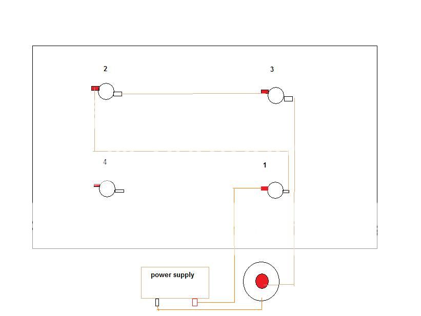
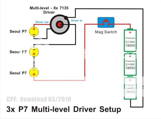
Ok guys, I thought this would be simple, but I am obviously doing something very wrong. I am trying to light 4 leds using a simple 1 mode 1*amc7135 driver. I am using the above picture as a model, the first 3 leds drop voltage then input to the 7135 driver and out to the last led. My power source is variable bench power supply and I have tried from 9V to 16V. What I am confused about are the lines to the top P7 led, where exactly do they go on the driver?
I made a very crude drawing of my setup here:

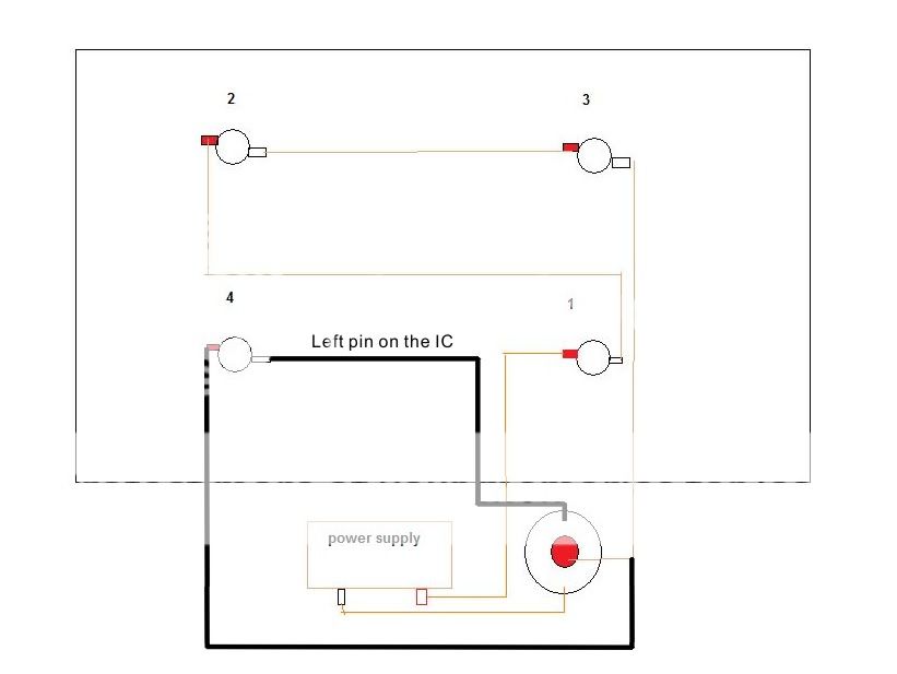
The problem lies in LED #4 which is connected to the driver. Where exactly do the red and black leads go? I have tried several different ways and they result in leds 1,2 and 3 lighting dimly and #4 not lighting at all. Obviously I am doing something wrong. I have tested all 4 leds and they are ok.
Currently I have the positive lead of led #4 connected to the driver out that is connected to the left pin on the IC and I have the negative lead of led #4 connected to the outer ring of the driver, common to my power supply ground.
Let me know if any of that is clear.
Thanks!
Ok guys, I thought this would be simple, but I am obviously doing something very wrong. I am trying to light 4 leds using a simple 1 mode 1*amc7135 driver. I am using the above picture as a model, the first 3 leds drop voltage then input to the 7135 driver and out to the last led. My power source is variable bench power supply and I have tried from 9V to 16V. What I am confused about are the lines to the top P7 led, where exactly do they go on the driver?
I made a very crude drawing of my setup here:

The problem lies in LED #4 which is connected to the driver. Where exactly do the red and black leads go? I have tried several different ways and they result in leds 1,2 and 3 lighting dimly and #4 not lighting at all. Obviously I am doing something wrong. I have tested all 4 leds and they are ok.
Currently I have the positive lead of led #4 connected to the driver out that is connected to the left pin on the IC and I have the negative lead of led #4 connected to the outer ring of the driver, common to my power supply ground.
Let me know if any of that is clear.
Thanks!
kwarwick
Newly Enlightened
This solution seem too good to be true, but after reading through the thread in detail it seemed like it was working for many people so I figured I'd give it a try for my application.
Tonight I tried using this setup to drive 3 x XMLs. Wired per the original post using a Shiningbeam 8x7135 board and three 18650s, the driver got very hot and started smoking in less than 20 seconds! I was measuring current draw from the batteries and it was under 2.8A so I'm not sure what went wrong. Just to make sure I didn't just have a bad driver I tried another but only let it run for a couple of seconds and I could see it was getting extremely hot so I curtailed my experiment to avoid frying a 2nd driver.
Any thoughts why this went *poof*? I'm thinking it might be due to LEDs with low vf causing the 7135 chips to work overtime or exceed their maximum voltage?
MikeAusC
Enlightened
. . . . Any thoughts why this went *poof*? I'm thinking it might be due to LEDs with low vf causing the 7135 chips to work overtime or exceed their maximum voltage?
Yes, the XM-L has much lower voltage drop than earlier LEDs - this means that with the same battery voltage, there's more voltage and therefore power being dissipated in the 7135.
kwarwick
Newly Enlightened
Yes, the XM-L has much lower voltage drop than earlier LEDs - this means that with the same battery voltage, there's more voltage and therefore power being dissipated in the 7135.
Darn, I was afraid this as the case! Now I need to figure out another driver solution for the DRY 3 XML host I'm trying to build up. Very challenging to find a driver that will handle 3 XMLs driven by 3 Li-ion batteries.
ma_sha1 did it, he added a resistor inline successfully. :thumbsup:
http://www.candlepowerforums.com/vb...-Yard-Sweeper-Mag-2C-3-mode-with-3x-IMR-22430
http://www.candlepowerforums.com/vb...-Yard-Sweeper-Mag-2C-3-mode-with-3x-IMR-22430
OldNick
Newly Enlightened
Yes, the XM-L has much lower voltage drop than earlier LEDs - this means that with the same battery voltage, there's more voltage and therefore power being dissipated in the 7135.
Just OOI, is there _that_ much extra work to be done? As I see it (may be brain fart day) if the voltage were half (4:2), there would only be a bit extra.....unless the chips are rtight at their limit at 2.8A. At 2.8A should the chips not be heatsinked anyway?
Similar threads
- Replies
- 7
- Views
- 2K


