PWM Regulator for Mag C body, JM-PhD-C1

JimmyM

Flashlight Enthusiast
Joined
Aug 30, 2006
Messages
2,853
Location
Boston, MA, USA
I'm starting this thread to see about feedback/design ideas for a Mag "C" body size version of my PWM regulator.
This is not a purchase/signup thread. When the time comes, a new thread will be started in the appropriate area.

This too is a spin-off of the design work that Alan_b, wquiles, myself, and others have been working on. The basic theory, design, software, etc have been developing for a while over in this thread. HERE

This version will be similar to the JM-PhD-D1 (Part1, Part2) in that it uses the same microcontroller and PWM just in a smaller diameter.
I have a schematic done and a PCB design in the works.

I'd like to get some feedback regarding feature set, operation, etc
Since this design will be incorporated into an existing Mag switch. You have 2 options.
1) The internal circuit is completely dead when off and it will only leak as much current as the MOSFET itself will allow. That's in the area of a few nano or micro amps. However, you're limited to just ON or OFF operation (with softstart of course).
2) The internal circuitry is live (but will sleep). This will leak more current due to the voltage sampling divider and the circuitry using some small amount of current. In the area of a few hundred micro amps. But this will allow things like multiple levels.

However, this could just be made software dependent like the JM-PhD-D1. It could be wired for ON/OFF operation with one software version or wired for multi-function control using a different software version.

Also, there is the subject of adjustability. There is no room for adjustment POTs so all voltage adjustments will be made by reprogramming.

Voltage limits will be the same as the JM-PhD-D1. 40V max with similar power handling.

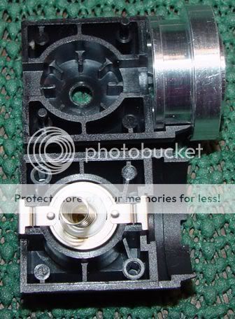
Now there's the big question of mounting. The PCB I'm working on is 26mm in diameter. I've placed 2 holes in the PCB to accomodate the screws/posts of a KIU ceramic socket.
So I thought it could just be mounted to the top of an existing C body switch after the post and post mount has been removed. This way 2 holes would have to be drilled into the top of the switch body to accomodate a pair of short posts. The PCB would be placed on top of the posts. The socket posts could then just be screwed into the ends of the posts under the PCB.
I've designed the PCB to keep the components facing the switch. Heat might be tough to deal with.

I'm really open to suggestions here. Of course any updates/fixes that come out of the JM-PhD-D1 testing will be incorporated into the C body design.

Thanks, all.
 
Last edited:
Thanks. I really have to start working on a proper UI like you have though. I'm really liking the ability to add/change functionality using "extra" pins not otherwise in use on the Tiny84.
I'm going to try to use as many of the unused pins as extras. I have 3 on the D1, the C1 should have room for 1 or 2.
 
Great work Jimmy,

I love that we will soon be able to have regulators available for incan mags. They make me more comfortable lending my lights out to others who are not so familiar with lithium rechargeable batteries.

I would like a simple on/off version, soft start with low battery cut off. Multiple levels would be nice, but I imagine more complicated to install?

I see the 2C/3C mags becoming very popular with the new AW 26500 cells and a regulator.

Cheers,
Nova
 
I see the 2C/3C mags becoming very popular with the new AW 26500 cells and a regulator.

I might have a Mag C or two around here someplace :whistle:
2z4jr4j.jpg
Just keeping the 26500's voltage [:poof:] under control will be worth it.

:popcorn:
 
Last edited:
Jimmy, the drop in setup that AW uses for his C model set the standard, and I recognize that the expense & design of the aluminum tube/sled is a tough one...so I understand your idea to follow the AWR model of mounting the chip on top of an existing, cut off Mag switch (C Mag in this case).

Besides the obvious multi-level, soft starting that AW has done.....the two big needs that come to mind are regulated voltage, and an adjustable low battery voltage to protect the IMR 26700 or 26500 size cells from over-discharge.
Yeah, the sled design is Alan's bag of tricks. If the "top of the switch" design isn't attractive to folks perhaps this will be a non-starter. There has been interest in a C body regulator so I figured I'd at least test the water.
 
I think there would be a large demand (+100 units). There would be those that would want it made and set as a drop-in (most of AWR's ended up being set for a particular light), and a few that would be interested and able to custom set AVR program items.

Once someone experiences a regulated voltage light, it is almost impossible to go back to direct drive. Problem is that most members that have been here for the last 1-2 years have not experienced the AWR type regulated driver. AW's is nice, but they are still direct driving and blowing many bulbs.
 
Lux is correct. I joined right after AWR options stopped being available and have only seen/known AW's since. Even looking for AWRs mythical spreadsheet to download, I have reached only dead-ends.

The question on sales is cost/benefit. Plenty of people still buy the Kiu sockets and those require cutting down a stock switch, but they're also not $100. Assuming sled design & manufacturing also add to the cost, then the 'trouble' of making our own complete units is happily offset by the savings from the difference. And trepidation over mistakes or reversibility can be offset by offering extra donor switches:

http://maglitesales.com/maglitestore/Replacement-Parts/Maglite-C-Cell-Switch-Assembly-Kit-12
 
Did somebody say C mag :duh2: :naughty:

I'd like a few....Multi level would be good...as main heat will be from high setting/ lamp, so it would be good to step down a level or two when it gets to hot on high.

I'd like to be able to set it up for different lamps. ( but would probably stick to the 458, and 633 or lower wattage.

One thing i'm not quite following is the "post" thing; The C mag Kiu socket kinda fits inside the C mag switch once its been pulled apart. (I'm sure you know) but there are no holes on the C socket ( that I can remember anyway) other than the two for the socket posts to screw in.

Can this go behind the switch? and sit where the +ve connection of the switch is? As for the 100W lamps on the kiu'd C switch the posts have to be removed, and the ceramic socket sits right ontop of the alu. heat sink. And it will keep the heat down on the board.

It will be great to have a low voltage cut off, but one thing to remember is if the cut of is 3V per cell, and you make it a 15V overall cut off for 5 series cells, then the cell with the lowest, capacity...( even buy 50- 100 mAh ) will drop down way below 3V, and the others will still be sitting at around 3.5V-3.6V Before we hit the 15V cut off.

So I would opt for an adjustable cut off....And match the cappacity of my cells as best I could, and trim it down over time, and checking the cells after a full run.


:popcorn::party::paypal:
 
My vote is for underneath the Kiu alumn pedestal. Looks like you can cut off the bottom skinnier portion of Kiu's alumn pedestal which accomplishes two things, leaves room for the regulator allowing the remaining top alumn pedestal to be your heat sink - just like in your upcoming D size MAG solution.
DSC02886.jpg


So I thought it could just be mounted to the top of an existing C body switch after the post and post mount has been removed. This way 2 holes would have to be drilled into the top of the switch body to accomodate a pair of short posts. The PCB would be placed on top of the posts. The socket posts could then just be screwed into the ends of the posts under the PCB.
I've designed the PCB to keep the components facing the switch. Heat might be tough to deal with.
 
Last edited:
My vote is for underneath the Kiu alumn pedestal. Looks like you can cut off the bottom skinnier portion of Kiu's alumn pedestal which accomplishes two things, leaves room for the regulator allowing the remaining top alumn pedestal to be your heat sink - just like in your upcoming D size MAG solution.
DSC02886.jpg

Hi Jimmy

I would love a C regulator just like (almost) your D version.

Physical fitting ?

Rather than screwing directly into the plastic of the C-switch it should be fairly easy to make a simple 22.5mm (aluminium or plastic) disk with 2 M3 threaded holes for the standoff posts, a central (pos) hole and an offset bottom (neg) hole. 2mm thick approx. There looks to be a fairly easy route for a constant POS if needed.

Mockup with 10mm standoffs (cnjl3's Photo)

mountjmcx11.gif


Don't know if there is room to fit the programming plug topside ? May get very hot and larger bulbs don't use the 10mm standoffs - just a nut or 2 as spacers in my KIU mods.

Cheers
Pete
 
Last edited:
Just a thought - there is some room on the rear of the switch.
About 4mm. Heat advantage for electronics?

Most people know 2 AW C 3300maH cells don't fit in a 2C.
I just put a 1 x C NiMh and 1 x C LION 3300 without a spring in a 2C Mag - tailcap goes on and I can hear the batts rattle. ie switch could extend 3-4mm rearward and only require cutting tailcap spring. I can't remember if AW Cs were 53mm or 53.5mm , but the new 26500s are shorter:sssh:

A regulted 2C 5761 would not need many bells and whistles to interest me.
Softsart , regulation , low batt cutoff. Sweet.
 
I've been thinking on and off about this.
I like the idea of the DIY approach (like the JM-PhD-D1), but packaging still continues to be a problem. The entire regulator would only be ~4mm thick.
I might be able to come up with a way to pot it in epoxy for mounting between the batteries and switch, but that might mean that 2 26500s might not fit into a 2C body.

Just for giggles I'm going to try to dead-bug a regulator inside the C switch body for multi-level ROP-HI. Probably just low and high. The power handling would be doable perhaps for a 5761 as well. But I don't see this as a solution for making a few dozen.
 
Been Thinking on this also, on and off;

Whats the max power people are thinking on these.

7C maglite is the most I have, so 5 Emoli, or 7 AW.

FM has done a load of 5 C's...And if your lucky enough you have a 5, 6 or 7 C Mag

So I'd say max for a regulated C mag Switch is 29.4V.,

but nominal would be ~24V on 7 AC IMR C's
I'd probably be using 5 Emoli ( or equivalent,) or maybee A123.


( But If we go A123 ( 26650) then we have more space inside C mags cause they dont fit as evenly as 26700 do in the mag sizes, so that gives more room.

I'd Like

A trim pot for V bulb adjustment,
A low ( realy low for heat reduction low + for runtime)
A HIGH :)
& a low bat cut off,


I think even though the C mag switch is good, an option could be a regulated "C sized" switch, might be the way to go, look at using all the area left by a removed c switch, & use it to fill with regulated goodness, even if it does over-run the boudary in to the body of the light a little....We'll make it fit :naughty:
 
Last edited:
How much space is inside of that Kiu pedestal? Would a JM-PHD-C1 "sandwich" be possible? Two boards carrying the components with standoffs between them? (Possibly utilizing the standoffs as electrical paths as well.)

Although it may complicate the design slightly it might give you just enough room.
There's almost no room at all.
 
Jimmy,

I have a Mag 2C that Mac bored for me to take 2 of AW's 26500's. There is very little room between the switch and batteries without modifying the spring/tailcap for extra length. The spring tension is very high (I am already thinking of trying to find someone locally who can seat the spring further into the tailcap), adding more length behind the switch would require work.

Would there be enough room inside the Kiu base if it was a "D" style fitting and screwed on top of the C switch instead of fitting into the switch? You then have room inside the switch and the Kiu base to work with. I haven't pulled apart a C switch so I only have the posted pics to go by.

I am happy enough to go without a pot for voltage adjustment, I don't see many adjustments being made after the light is assembled for the first time.

Keep up the good work on this and the ROP D reg's.

Cheers,
Nova
 
Top