repairing a Supernova Triple dynamo headlight

Steve K

Flashlight Enthusiast
Joined
Jun 10, 2002
Messages
2,786
Location
Peoria, IL
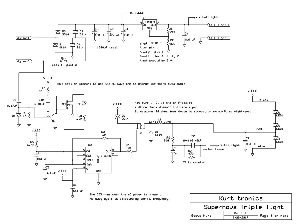
It would be intriguing to hear from the Supernova designer to learn why he/she made some of the choices. The choice to use analog circuits made it possible for me to reverse engineer it, but I can only guess about the details of the circuit that feeds the dynamo signal into the 555-based buck converter. It seems like they are trying to modify the buck's duty cycle in order to extract the max power from the dynamo... but that's just a guess. If I ever find the spare time, it might be fun to simulate the circuit and get a better understanding of what is going on.

Of course, the proper way to do it would be to just use a micro controller for the buck controller (and I have some issues with the tail light circuitry too), but it would be much harder to fix! Boy... I really need to find time to tinker with bike lights again!
 

8trackDirtPlayer

Newly Enlightened
Joined
Mar 25, 2015
Messages
4
Fantastic write up, thank you for sharing! I have encountered an issue with my E3 Triple 2 recently and will be referencing your story as guidance during my attempt at repair. Thank you!
 

Steve K

Flashlight Enthusiast
Joined
Jun 10, 2002
Messages
2,786
Location
Peoria, IL
Glad you enjoyed it! I was just happy that it worked when I was done with it!

It was nice of Supernova to design the light with relatively generic parts and not do anything too confusing to reverse engineer.
If you have a multimeter, you should be able to troubleshoot most of the circuit. The buck converter, based on the LM555, is about the only place where a 'scope is useful. Even then, you should be able to poke around and get some idea of whether it is alive, and in the worst case, just replace parts that look questionable... they are cheap enough.

The only hard part is taking off the small board with the switch, as well as desoldering the 8 pin SOIC packages. ....well.... desoldering an LED was pretty tricky too. It seems unlikely that an LED would be damaged, though.

Let me know how your repair goes!
 

dynohub

Newly Enlightened
Joined
Jan 8, 2018
Messages
5
Hi Steve,

Many thanks for your excellent work and for sharing, it has been a great help :) I have been trying to modify my E3 dynamo light so that I can take 5.2V off the regulator via the tail light contacts to charge a USB battery pack and I'm almost there thanks to your post - all I have had to do it change the regulator R2 to a value of 680R to get 5.2V. The bit I'm currently stuck on is figuring out if and how I can get the tail light (USB) to carry on charging even when the front light is switched off? Ideally, my hope is to use the switch on the E3 to toggle between front light and USB charging and if I then remove the load from the USB charging wires (tail light) by disconnecting the powerpack I efectively turn it off to reduce dynamo resistance? I hope that makes sense?

May I ask if you think this idea might work?
 

Steve K

Flashlight Enthusiast
Joined
Jun 10, 2002
Messages
2,786
Location
Peoria, IL
Hi Steve,

Many thanks for your excellent work and for sharing, it has been a great help :)

no problem. Feedback like yours helps justify my urge to document projects like this. :)

....The bit I'm currently stuck on is figuring out if and how I can get the tail light (USB) to carry on charging even when the front light is switched off? Ideally, my hope is to use the switch on the E3 to toggle between front light and USB charging and if I then remove the load from the USB charging wires (tail light) by disconnecting the powerpack I efectively turn it off to reduce dynamo resistance? I hope that makes sense?

May I ask if you think this idea might work?

One thing that I enjoy about the design of the Supernova is that they use the LEDs as a way to clamp (i.e. limit) the voltage out of the dynamo. The high source impedance of the dynamo lends itself to this sort of shunt regulation.

Unfortunately, if you aren't using the LEDs to load the dynamo, then you can see some very high voltages out of the dynamo. This problem increases as the current drawn from the dynamo decreases.

If you were to feed the output of the full wave rectifier to the LM317, there would be a voltage where the LM317 would be damaged. Looking at the datasheet, it says that the absolute max voltage between input and output is 40V. With a 5.2V output, that means that anything over 45.2V out of the rectifier could damage the LM317.
My recent measurements of my 1st generation SON dynamo showed that with no load, I would get 29VAC at 20mph. This is about 40V peak, so anything over 20mph is getting close to potentially damaging a LM317, and as a result, possibly the device being charged via the USB connection.

One option would be to design a high voltage series regulator. Another option would be to use a shunt regulator to get the desired 5.2V. It'll still use up to 2.5W or so, but that's less than the power used by the Supernova when it is on.

Another option would be a switching regulator (buck converter) designed to operate with high input voltages. This could provide more current for charging the powerpack than a linear regulator such as the LM317. There are ones designed to be used in automotive applications that can handle 60 to 80V (IIRC), and might be a good solution. My instinct would be to buy the parts and design and build one myself, but I'm going to guess that someone sells these on ebay. Not sure if you can trust their design or not, though.

Have you considered the assorted issues associated with charging lithium batteries? There are limits regarding temperature, state of charge of the battery, etc. .... or does the powerpack take care of that? I'll guess that it does.

Well, those are some ideas. There are pro's and con's to each of them.
Another idea would be to buy a commercially built device such as the Sinewave. No personal experience with the device, but I've heard good things about it.
 

dynohub

Newly Enlightened
Joined
Jan 8, 2018
Messages
5
Thanks for your reply, it looks like you saved me from burning my light through lack of knowledge ;-)

I've looked around for ages at all sorts of products to match what am aiming at but nothing quite fits so I thought the E3 might be a suitable starting place for a hack :) In essence I'm trying to implement a neat setup which allows the dynohub to power a front light or charge a USB power pack with an easy switchover between the two. The plan is to have the E3 permanantly installed so the light can be switched in at will, for longer trips I would then be able to plug in a USB compliant battery pack based on lithium cells with integrated charge control etc - this means I wouldn't be risking charging a phone or GPS directly. During the day the power pack can charge up ready to be used as required and then by night I can swap over to the light. I'm hoping to be able to keep all the electronics within the E3 case for neatness and have the tail light wire port (I'm not using dynamo tail lights) used to host a short cable with waterproof connector so I can plug in the USB power pack via a custom cable when required..... it could be a very neat solution if it can be made to work. I think there is enough space on the light to fit a toggle switch that could be used to switch between the LEDs and USB output so I guess the challenge is to design a compact and efficient circuit to handle the high voltages and deliver stable 5.2V. I have attemped to design a circuit based on the MIC2940A regulator with a varistor to try and clamp voltage spikes at the input but I don't have enough knowledge to know if this is any good or will even work properly? The attached is where I got to with it, I included a 5F supercap to buffer the output a little but this could be included in the custom USB charge cable with the rest possbibly fitting in to the E3 housing. Alternatively there might be a nicer design, I'm wondering if your suggestion to use a shunt regulator might be a good option as it seems like it would be a more compact solution to fit into the E3 case?

Thanks for listening :)

kebtdf.jpg
 

Steve K

Flashlight Enthusiast
Joined
Jun 10, 2002
Messages
2,786
Location
Peoria, IL
a few thoughts on the schematic:

1. a varistor, such as a MOV, is intended to handle transient voltages such as ESD. It's not designed to handle steady over-voltage conditions. That is more of a job for a Zener diode. In this sort of case, I'd recommend something like a 1N5369, or another part from that family of 5 watt zeners. In this case, you'd want to be sure it clamps the voltage below 60V at the current that the dynamo can supply. I'm certain that the dynamo won't be sourcing 500mA at 60V... but it might still be 300mA? 200mA? 100mA? This is probably something you'd want to run a test to determine. Of course, if you've got even 100mA going through a 55V zener, that's 5.5 watts of power being wasted (and exceeding the limit for a 1N53xx zener). Not a great scenario.

2. There's not much reason to put a supercap at the output of a regulator that is going to feed a USB device. Maybe 100uF? In the case of a Low Dropout regulator like the MIC2940, stability can be a concern, and it's best to use what the datasheet suggests. Some LDOs can be extremely sensitive to the impedance and value of the output cap(s)!

As you note, this is a lot of fiddling around to get something that works. The ideal and efficient solution would be a buck converter that can handle input voltages of 100V or so. The automotive market has been driving things in that direction, so maybe there's something close enough now??

The alternative is a precise shunt regulator. A power zener diode like the 1N53xx might be good enough. I'm really not sure what the tolerance is for the 5V on a USB source. Zeners aren't designed for precision, though, so an alternative is to use a precision voltage reference with a transistor to handle the power. The LM431 datasheet has a schematic for this sort of thing...
http://www.ti.com/lit/gpn/lm431
See figure 19 on page 16.
Don't forget to provide some heatsinking for the transistor!

Did I miss any questions??
 

dynohub

Newly Enlightened
Joined
Jan 8, 2018
Messages
5
Thanks for the very useful pointers, I was assuming the over voltage from the dynamo to be transient so good to know about the zenner option. I think I'm close enough now (thanks to your help) to experiment with the circuit below - I can swap out parts like MOV/Zenner and output caps with relative ease if I find issues. I think I've worked out how the whole thing can fit neatly inside the E3 with a toggle switch to divert from the light to the 5V USB. I will start playing and post how it all goes.

Thanks once more for your help, its great learning new stuff.

9kpc9k.jpg
 

Steve K

Flashlight Enthusiast
Joined
Jun 10, 2002
Messages
2,786
Location
Peoria, IL
Always glad to see a project make progress!

After looking over the circuit, a mini-design review, a few things caught my attention....

1. isn't a bridge rectifier still needed? Or is this using the Supernova's bridge rectifier?

2. The Vishay 56V zener is not a bad choice, but.... there are two things that might be a problem.
2A. The first is that the MIC2940A is rated for 60V transients, but not 60V steady-state. The datasheet isn't entirely clear on this, but it does say: Key MIC2940A features include protection against reversed battery, fold-back current limiting, and automotive "load dump" protection (60V positive transient)."
The load dump pulse is somewhat short.. less than a second. Subjecting the regulator to a steady 60V will cause it to heat up quite a bit, depending on how much current is passing through the regulator. The datasheet does say "Operating Input Supply Voltage .......................... 2V to 26V". As such, operating at higher voltages is not encouraged.
2B. I believe the intent of the zener is to handle the dynamo's power when the battery is fully charged and no current is being drawn from the dynamo. The datasheet for the Vishay zener does suggest that it can handle 300W of power, but... what it is actually saying is that it can handle a short pulse that delivers 300W to the zener. Page 1 of the datasheet provides a more realistic indication of the steady-state power dissipation, which is 1.25 watts. The data that I have for a SON dynamo shows that at 20mph, it can supply 0.4A into a 20V load, which is 7.8 watts. The open-circuit voltage is about 29V, so if you have a 26V zener diode, I'm not sure how much power will be dissipated in the zener, but it's probably a good deal more than 1.25W. For this reason, I'd recommend using a 3W or 5W zener diode with a 26V zener voltage. Something like a 1N5360B should be good.

3. There may be value to using a larger input filter cap. The charger circuit in the power bank might be happier with a steady input current instead of a pulsing current. Or maybe not?? I really don't know. If you see signs that the power bank isn't charging correctly from the dynamo, but works fine when powered from a plug-in converter, then you might try a larger capacitor for C5.

That's all that comes to mind at this time.
Good luck!
 
Last edited:

dynohub

Newly Enlightened
Joined
Jan 8, 2018
Messages
5
Hello again, that's very kind of you to review this and feed back :)

I've updated the schematic below inline with your suggestions: using a 5W zenner now and a 22uF 50V tant cap on the input. I have omitted the bridge rectifier as I was hoping to connect this to the wires coming from the E3 controller board to the LED chip. I guess this is simply a rectified output from the dynamo?

syp8ir.jpg
 

Steve K

Flashlight Enthusiast
Joined
Jun 10, 2002
Messages
2,786
Location
Peoria, IL
hmmm.... actually, you could tap off of the rectified power in the E3, which is indeed the voltage applied to the LEDs. Since the light's power switch is in series with the dynamo power, you would have to have the light turned on in order to charge the battery. To be honest, this wouldn't be a bad arrangement. The battery would absorb most (all?) of the current when it needed to be charged, and then the LEDs would start using more current as the battery charging started to taper off. It wouldn't require the zener diode at all, since the LEDs are effectively clamping the dynamo voltage.

33017901146_0fb78fa252_b_d.jpg


Being a bit too lazy to go back through the thread and check, I seem to recall that you might have been planning to have the light off while charging the battery. For a lot of other dynamo lights, that might be required. For the Supernova, you might not need to.

My only concern is that there is a weird low-speed mode on the Supernova, where it uses a buck converter to supply current to the lowest LED. It might still draw current while the battery is charging, so perhaps you'd need to go back and turn off the Supernova, and have a dedicated bridge rectifier and zener for the battery charge circuit. It might take some test runs to see how things work out.
 

dynohub

Newly Enlightened
Joined
Jan 8, 2018
Messages
5
Hi, Thanks again - just a quick note to say that I have now designed and ordered a PCB based on the above. Would you like me to send you a populated one to play with when it all arrives?
 

Steve K

Flashlight Enthusiast
Joined
Jun 10, 2002
Messages
2,786
Location
Peoria, IL
best wishes with the PCB. Translating a circuit from the schematic to copper can be an adventure and learning experience all by itself! Usually, it's a lesson in why engineers are very detail oriented. It doesn't take much of an oversight to reach an "aw sh*t" moment with circuit boards. :)
Fortunately, jumper wires and dremel tools can take care of a lot of these issues.

Thanks for the offer of a board, but I've got a few projects in the queue already. Need to make a taillight that isn't as horribly ugly as the one I have now, and want to try to fit an optic with a tighter beam into my headlight. ..and then there's that dead B&M Eyc that I want to bring back to life (or use as the base for some experiments.. a bit Frankenstein-ish, perhaps).
 

ArneMi

Newly Enlightened
Joined
Mar 28, 2022
Messages
1
Location
Hannover
Hi Steve,
I have a problem with my E3. It has stopped working without any external impact. I opened it up and found some sort of dried rust on the underside. Since the bike is always parked dry and is not cleaned with water, I suspect condensation. Or could electrolyte be leaking from the capacitor, for example?
After disassembling the electronics and desoldering the LED connections, it became apparent that there was no voltage on the input side of the LM317. The LED does not want to light up on the laboratory power supply either. I was not able to test the buck-bust circuit as I've only a DC supply available.
Since I have no in-depth knowledge of electronics, I am thinking about replacing the electronics and LED completely. Is there, for example, a completely cheaper lamp whose electronics and LED can be transplanted?
Many greetings
Arne
 

samsavvas

Newly Enlightened
Joined
May 11, 2017
Messages
28
Hi Steve,
I have a problem with my E3. It has stopped working without any external impact. I opened it up and found some sort of dried rust on the underside. Since the bike is always parked dry and is not cleaned with water, I suspect condensation. Or could electrolyte be leaking from the capacitor, for example?
After disassembling the electronics and desoldering the LED connections, it became apparent that there was no voltage on the input side of the LM317. The LED does not want to light up on the laboratory power supply either. I was not able to test the buck-bust circuit as I've only a DC supply available.
Since I have no in-depth knowledge of electronics, I am thinking about replacing the electronics and LED completely. Is there, for example, a completely cheaper lamp whose electronics and LED can be transplanted?
Many greetings
Arne
Arne, It sounds like the original driver is cooked! I can only suggest that you simply replace the proprietary driver board with a good quality replacement driver with the features you need & a size that will fit.
 

Steve K

Flashlight Enthusiast
Joined
Jun 10, 2002
Messages
2,786
Location
Peoria, IL
Hi Steve,
I have a problem with my E3. It has stopped working without any external impact. I opened it up and found some sort of dried rust on the underside. Since the bike is always parked dry and is not cleaned with water, I suspect condensation. Or could electrolyte be leaking from the capacitor, for example?
After disassembling the electronics and desoldering the LED connections, it became apparent that there was no voltage on the input side of the LM317. The LED does not want to light up on the laboratory power supply either. I was not able to test the buck-bust circuit as I've only a DC supply available.
Since I have no in-depth knowledge of electronics, I am thinking about replacing the electronics and LED completely. Is there, for example, a completely cheaper lamp whose electronics and LED can be transplanted?
Many greetings
Arne
I haven't been hanging out here for a while, so sorry about the delay. Rust is certainly odd... it might be a capacitor leaking and leaving a residue?? Photos would help. Still, there could be other problems, and it could be hard to work out what the problems might be.
As far as a proper power supply for troubleshooting... I think it might be worth putting a 12 ohm resistor in series with the power supply and turning the voltage up gradually to 12V. That should still limit the current... although you might want to monitor the current going into the light before going past 6V.

I'm completely without knowledge of whatever else might be worth putting into the housing. Honestly, the modern B&M lights are pretty good, from what I hear. Might be better to just buy one of them?
 
Top