Surefire L4 (KL4) with Cree MC-E

Energie

Enlightened
Joined
Nov 12, 2006
Messages
302
Location
Germany
Surefire L4 (KL4) with (stock) Luxeon 5: approx. 110 emitter lm
Surefire L4 (KL4) with MC-E: approx. 370 emitter lm
(Runtime is the same as before)


L4-1.jpg

The MC-E is small, not easy to solder
L4-9.jpg


Small heatsink
L4-10.jpg


KL4 head
L4-2.jpg


Disassembled.
L4-3.jpg


L4-4.jpg


Stock heatsink with luxeon5:
L4-5.jpg


Not enough space for the MC-E
L4-6.jpg

Milled out:
L4-7.jpg


New heatsink
L4-11.jpg


L4-14.jpg


L4-8.jpg


L4-15.jpg


L4-12.jpg


Cree MC-E.jpg


L4-16.jpg


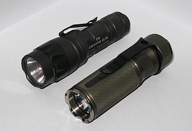
The result:
L4-18.jpg


KL4 with E1e body (and AW´s RCR123, protected)
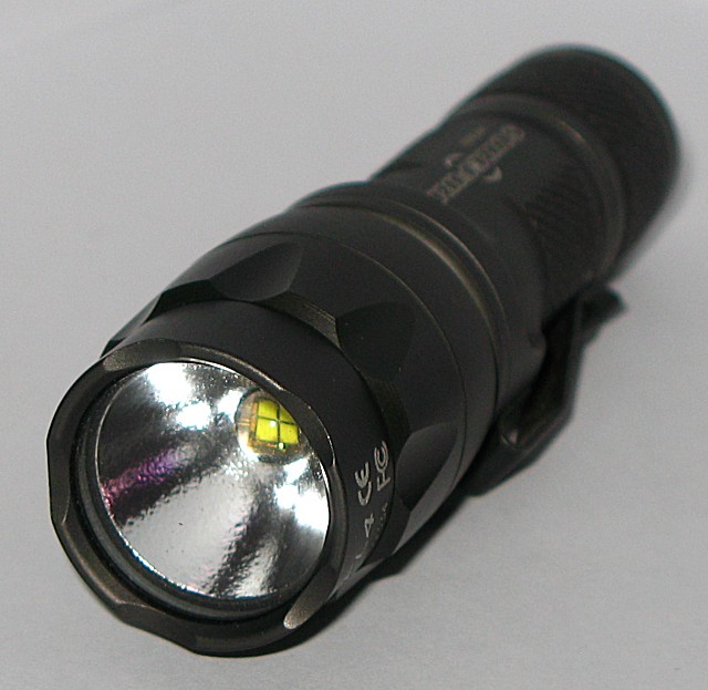
L4-19.jpg


L4-20.jpg


Beamshots are here: Surefire L2 with MC-E

IR-Scans with L4 (MC-E), L2 (Lux5), L2 (MC-E) are here: Link
 
Last edited:
Another beautiful mod! Again, very nicely done & I love your heatsinks! If you were to ever offer some I definitely be in for some.
 
Another beautiful mod! Again, very nicely done & I love your heatsinks! If you were to ever offer some I definitely be in for some.


Yes, I agree the mod is very clean!!:cool:
I have an MC-E in a KL4 and love it!

+1 for purchasing some heatsinks!!....should you decide to offer them:paypal:
 
And I JUST asked who could open up the reflector in a clean matter. Sir, that is gorgeous machining
 
That is some very professional looking work. When I saw the title, I cried because I thought someone had destroyed a perfectly good KL4. After I saw what you had done, I cried tears of joy. Fantastic job. :twothumbs
 
Nice mod Energie!
Do you know the bin code on that MC-E emitter?
Also how's the tint on it compared to the original LuxeonV?
I'm considering doing this mod, i took my KL4 head apart twice only to put it back together beacause i love the creamy white tint on my L4.
I just wish it had more lumens:devil:
 
Energie- Gorgeous mod! I've had my L4 for years now and I think it's time for an upgrade. I'm reasonably mechanical and electrically minded so I thought I'd take my L4 apart and see whether it all made sense. What I found when I took it apart was that the back of the reflector head looked totally different from your picture! Am I missing something or did they just make a big change somewhere in production on the head casting/machining? In yours it looks like the reflector head functions as a heatsink. In mine, there is no thermal paste on the LED heatsink and only those 2 small risers on the reflector head! Actually, it's kind of stupid since it seems like it would thermally isolate the LED heatsink.

Anyone else see this in their L4?

KL4ReflectorHead.jpg
 
Last edited:
See http://www.candlepowerforums.com/vb/showthread.php?t=237637

Put some thermal compound on those two risers. That's going to be your thermal path from the heat sink to the rest of the metal head. Also put some compound on the sides of the heat sink. There will be some contact with the inside of the head.

When you solder your leads to the tiny MC-E terminals, fit the stripped wire ends into the spaces between the MC-E terminals. That should take up the entire gap. Push the wire so that the insulation is snug right up to the MC-E terminals. Now your soldering task should be fairly easy and clean to do, with zero exposed wiring.

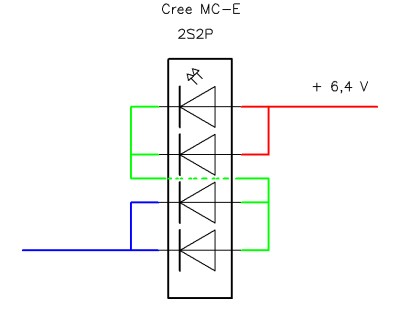
If you use the stock heat sink, you will have to drill two more holes for the 2S2P "crossover" wire. if you'll notice, the existing feed holes for the LED wires are slightly offset from 90 degrees to the screw holes. That's because the LED terminals are also offset. You want to drill your two additional holes to line up with the MC-E terminals that need to be connected. That way, your hookup wires can come straight into those spaces between the terminals.

Whether you have your reflector style or Energie's, there is no need to mill out a larger emitter slot to fit the MC-E. In both cases, just the barest filing of the MC-E's case corners will allow the LED to drop right into the emitter pocket. What is desirable, however, is some slight milling of the emitter pocket depth, increasing the depth by about 0.5mm. That will allow the MC-E die to sit higher into the reflector opening, giving you the ideal focus height for the die and the optimum beam.

Note, you will also have to shim up the MC-E by about 1.7mm, give or take.

If you don't mill the emitter pocket by the roughly 0.5mm, and you get too much "texture" in your beam for your tastes, you can try using some diffusion film to improve the beam. The downsides are that 1) the film can absorb about 10% or more of the beam, and 2) you trade off beam smoothness for a loss in hot spot intensity (fall off of about 1/2). However, you probably won't notice a 10% loss in lumens and the beam is quite floody anyway, so maybe hot spot intensity isn't a big deal. YMMV.
 
Last edited:
Justin Case-
Thank you SO MUCH for your generous contribution to my efforts! It's a big help. That link you posted is super helpful too. I would have found it except the search engine doesn't let you find things with such short names (L4, MC-E, etc).
It all makes sense and is a big help. And it looks like the old-style reflector head may actually be EASIER to deal with which is nice to see. I'm also glad to see that the poster had to cut the LED wires coming off of the driver board since like in my KL4, the wires dissapear into a glob of black electrical sealant.

One question that wasn't covered in the link you referred me to. You said:
"What is desirable, however, is some slight milling of the emitter pocket depth, increasing the depth by about 0.5mm" By that I assume you mean the area I've colored red in my attachment, right?
I understand the copper shim and will mill one as you've described. I can see it makes up for the extra depth you talk about milling above since the other threads talked about the shim being more like 1.2 or 1.3 mm.

Anyway, thx again!

-J

KL4ReflectorHeadred.jpg
 
I'm not clear on the "cut the LED wires" part. You don't have to cut off the existing LED wires, unless you want to change them for some reason. The stock wires work fine.

Yes, the red highlighted area is where you need to mill.

The exact dimensions needed for the copper (or whatever metal you favor) shim and milling of the emitter pocket depends on your specific measurements for your KL4 and your MC-E. Manufacturing variations exist. You should use some calipers to determine what dimensions you need for your specific case.

Another trick: use the reflector opening to self-center the LED. I would fit the MC-E into the emitter pocket and then thermal glue the shim to the LED first. Use those curved ribs and the MC-E case edges to help eyeball good centering of the shim on the back side of the MC-E. Let the glue cure.

With the second pair of holes drilled in the heat sink, remove the LED+shim from the emitter pocket and carefully glue the MC-E+shim to the heat sink and position the MC-E legs appropriately. Then slide the heat sink with MC-E into the head. This should automatically center the LED on the heat sink. If you did it right, the MC-E also should not shift its position enough to disturb where the MC-E legs are relative to the feed holes in the heat sink. You don't want the MC-E to rotate its position. Slight lateral movement is all you want to do the final centering of the LED on the heat sink. You can do this multiple times if it makes you more comfortable, checking the position of the MC-E's legs to convince yourself that all is well. Then leave the heat sink in the head and let the glue set. You could let the glue get slightly thick first and then do the fitting. The extra viscosity can help keep the MC-E from rotating around, disturbing the position of the legs. But don't wait too long!

What I do to help position the heat sink for smooth insertion into the head is to drop the bare heat sink into the head first. Align the screw holes. Then take a marker and make some tick marks on the rim of the head where the notches are on the edges of the heat sink. Those become your alignment marks.
 
Last edited:
Again, thank you tremendously for the advice! You're helping me and lots of others who will read these posts.
It was late when I mentioned cutting the wires... in reality you would unsolder them from the existing LED. What I meant was it was good to see that the wires don't need to be changed where they dissapear into the black goop since that would be tricky.

So it looks totally doable for me. I'll let everyone know how it all goes!

Thanks again to everyone to puts time into helping strangers on this site!

-Jesse
 
Top