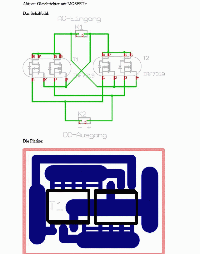
Ktronic,
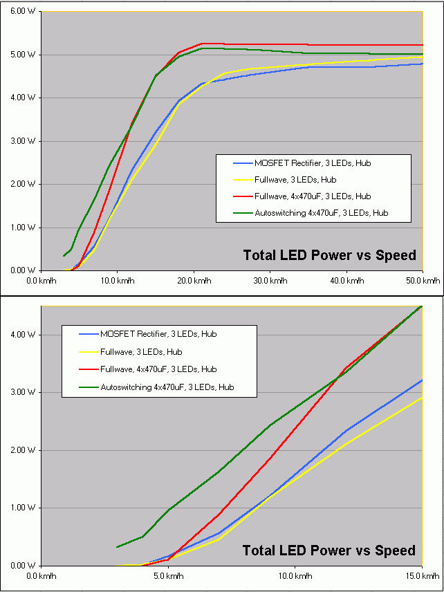
Back in Post #6 you have a very simple circuit which uses a bipolar capacitor. You then substitute 4 polarized caps in its place later on. I'm curious. Is there any advantage to the 4 polarized caps over the single bipolar other than ease of finding them at hobby shops? I really like the simplicity and size of the single bipolar circuit and I can get them very inexpensively.
Also with regard to the bipolar circuit. How did you go about determining the size of the cap? Was it trial and error, or do you have some equations tucked away somewhere that you'd like to share?
Thanks,
-Mike