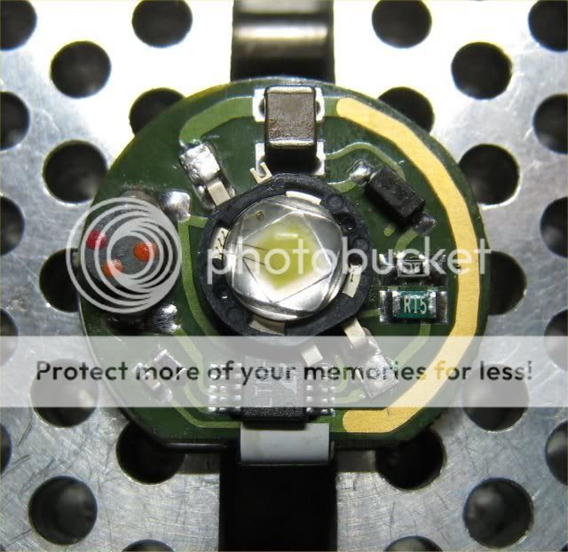
Where to get a few R15 SMT resistors?

Sinjz

Flashlight Enthusiast
Joined
Oct 4, 2003
Messages
1,120
Location
six blocks from ground zero - WTC/NYC
I've been sitting on a couple of stock Arc LS's for awhile. I'm finally getting around to modding them and would like to up the current. I think they currently run at around 450 ma and I read that if I add a second R15 SMT that it will be boosted up to about 667 ma. Is that right?

Does anybody know where I can find a few R15 SMT resistors? I'm not looking to buy a hundred of them or anything, just want three or four. Thanks. :)
 
I've modded a lot of Arc LS boards using the 0603 resistors. They're long enough to touch both pads so it's no problem using them.

Also when using P4s without a shim, depending on the reflector if used, I recommend moving the inductor further out so the reflector doesn't touch it like pictured below. I find that reflectors like McR-18S will touch the inductor & crack it when it's all screwed together. I also pot my inductors for added safety.


Img_0916.jpg
 
Thanks for the link and info guys, but OMG!!! :eek:oo: Those suckers are tiny. I'd have enough trouble with the 1206 size ones. :eek:

BTW, is it possible to accidentally destroy these if I hold the soldering iron on it for too long or something? Soldering is not a skill I'm very good at. :crazy:

Anybody know how to calculate what current I';d get if I use other resistor values?

Yes it is possible to damage the sense resistors by applying excessive heat to them with a soldering iron. The pads can fall off.

The circuit is pretty much Wayne's Badboy. Calculate the parallel resistance of both resistors & divide 0.05 by the parallel resistance to calculate current. ie 0.15 + 0.15 = 0.075, 0.05 / 0.075 = 0.666666666666667. Or you can forget all the mumbo jumbo & just use Wayne's Calculator. :grin2:

Personaly I prefer 611ma (just add .18 along with the stock 0.15) for a better balance of runtime & brightness. Most people mod Arc LSs to 667ma. I can mod the board for you if you need help. I can also repair them too if needed. I have the inductors, ICs, upgrade diodes, & sense resistors on hand. PM me if you need help.
 
Hehehe.... I took the R15 off one board and added it to another just to see what would happen. :)

No prob tinning the ends of the R15, but I had such a hard time trying to get it to sit in place while trying to put the soldering iron to it so it would melt. :ohgeez: Not a great soldering job, but it's on there.

But there's a problem. I measure a current of about 460-480 ma on my meter. According to the link darkzero provided it should have gone from 350 to 667 ma. What do you think may have happened?

Darkzero, you mention your preference for 611ma. Is that only for the luxeon or for the ssc P4 too? I plan on upgrading the emitter like CM suggested.

BTW, what would happen if I used a zero ohm resistor to bridge the path? :crazy:
 
..But there's a problem. I measure a current of about 460-480 ma on my meter. According to the link darkzero provided it should have gone from 350 to 667 ma. What do you think may have happened?

Sounds like the circuit doesn't see the second resistor which should be in parallel with the original. Also the current to the LED is 0.05V/R so stock is 333mA with one 0.15 ohm resistor, and 667mA to the LED with two resistors in parallel. You should see about an amp of current from the cell with the resistors in parallel.

...BTW, what would happen if I used a zero ohm resistor to bridge the path? :crazy:

Don't do it. It will try to pump as much current to the LED as it can, more likely it will malfunction, worst case, you can damage the converter. With the size of the Arc LS, 667mA to the LED is probably as high as I'd go due to heat. You'll still get a lot of light and a more reasonable runtime.
 
Sounds like the circuit doesn't see the second resistor which should be in parallel with the original. Also the current to the LED is 0.05V/R so stock is 333mA with one 0.15 ohm resistor, and 667mA to the LED with two resistors in parallel. You should see about an amp of current from the cell with the resistors in parallel.


Don't do it. It will try to pump as much current to the LED as it can, more likely it will malfunction, worst case, you can damage the converter. With the size of the Arc LS, 667mA to the LED is probably as high as I'd go due to heat. You'll still get a lot of light and a more reasonable runtime.

So do you think I should add more solder? Maybe try removing and resoldering it? Does it matter if I have a solder blob that connects the R15's? :thinking: :sigh:
 
Hehehe.... I took the R15 off one board and added it to another just to see what would happen. :)

No prob tinning the ends of the R15, but I had such a hard time trying to get it to sit in place while trying to put the soldering iron to it so it would melt. :ohgeez: Not a great soldering job, but it's on there.

But there's a problem. I measure a current of about 460-480 ma on my meter. According to the link darkzero provided it should have gone from 350 to 667 ma. What do you think may have happened?

Darkzero, you mention your preference for 611ma. Is that only for the luxeon or for the ssc P4 too? I plan on upgrading the emitter like CM suggested.

BTW, what would happen if I used a zero ohm resistor to bridge the path? :crazy:

Yes I like 611ma, doesn't matter if it's a Luxeon, P4, or Cree. When I used the LS stock I remember it having great runtime. Then bumping up the 667ma (like everyone else was doing at the time) I noticed a big hit in runtime compared to stock. I find 500ma - 611ma is perfect for my liking with better runtime. Not as bright as 667ma but it's not very noticeable unless comparing two lights side by side.

You mentioned measuring 460-480ma, how exactly are you measuring? Are you measuring current at the battery? Is your battery fairly fresh? To measure the drive current you must measure it at the emitter. Meaning you will have to break the connection on one of the emitter leads from the board & connect your multimeter in series between the emitter lead & the pad on the board.


So do you think I should add more solder? Maybe try removing and resoldering it? Does it matter if I have a solder blob that connects the R15's? :thinking: :sigh:

If the resistor is securely soldered on then it should be fine, adding more solder won't do anything. If you're measuring correctly as I mentioned, possibly the resistor got damaged by too much heat from the soldering iron causing it to give a different value? Unlikely & I doubt it but it can happen. Or is your inductor cracked or chipped? A broken inductor will cause low output but usually it's very dim where you definitely know something is wrong.
 
...
You mentioned measuring 460-480ma, how exactly are you measuring? Are you measuring current at the battery? Is your battery fairly fresh? To measure the drive current you must measure it at the emitter. Meaning you will have to break the connection on one of the emitter leads from the board & connect your multimeter in series between the emitter lead & the pad on the board.

I measured with the whole thing reassembled and with the battery sticking out the head. I guess, that's battery draw. Still I was using a semi-fresh cr123, so unless my emitter is incredible, I was not seeing 667ma at the emitter. :(

If the resistor is securely soldered on then it should be fine, adding more solder won't do anything. If you're measuring correctly as I mentioned, possibly the resistor got damaged by too much heat from the soldering iron causing it to give a different value? Unlikely & I doubt it but it can happen. Or is your inductor cracked or chipped? A broken inductor will cause low output but usually it's very dim where you definitely know something is wrong.

It's still bright, just not brighter than before I did the mod. Definitely not super dim, so probably not a problem with the inductor. I think CM got it right and somehow the 2nd r15 resistor isn't being read as connected. I'll probably try adding some solder this weekend and if that doesn't work, remove and try to do it again. :sigh:
 
Top