XM-L Dive Light Input Needed

BlackAndChrome

Newly Enlightened
Joined
Jun 29, 2010
Messages
19
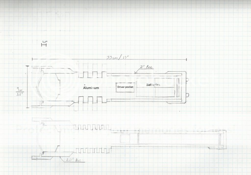
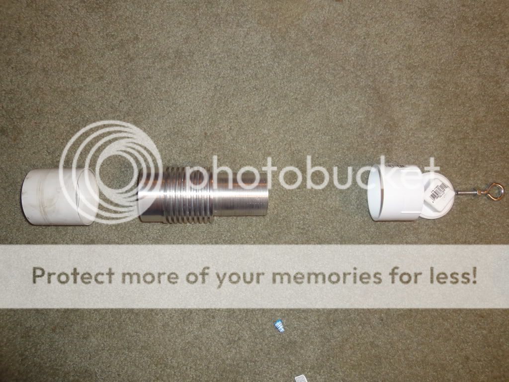
I've decided to build a dive light that I plan on using this summer when snorkeling on vacation. I've already done a few XR-E and XP-G mag mods including the heatsinks so I figured it would be interesting to take it to the next level. Especially since I have a good reason to throw some money at it.

Here's the basic thought.

Flashlight.jpg


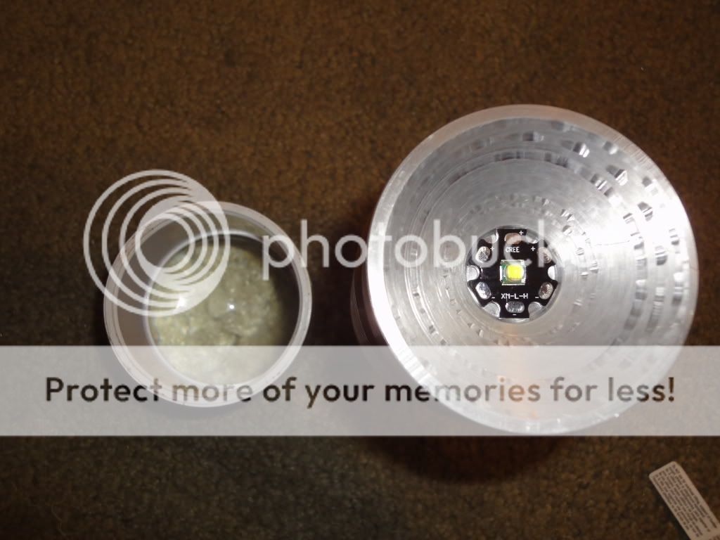
Light engine is a Cree XM-L with 3 single mode 1050mA drivers I may add another AMC 7135 to one of the drivers to drive it at 3.5A. No reflector and a DealExtreme 66mm aspheric lens. Batteries are 4xELITE 5000mAh NIMH Sub-Cs.

All of the above components have been ordered so I'm not just speculating :grin2:

Now what would be the best way to switch this? I was thinking reed switches and power mosfets representing 3 different modes. The first reed switch would control a power mosfet connected to one driver while another reed switch and mosfet would turn on the other 2 drivers. Therefore the twist ring would have 2 magnets on it that line up with each reed switch. One magnet on on reed switch would give 1/3 power, one magnet on the other would give 2/3 power and both lined up would give 100%

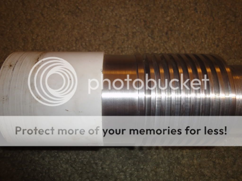
General question, what would be the best way to seal the PVC to the Aluminum main body and the lens to the PVC? I was thinking about making grooves on the lathe and using casting epoxy but I had concerns about thermal fractures considering the likely difference in expansion rates between aluminum and PVC. PVC to PVC will obviously be purple primer and cement.

Thanks in advance for your responses to my long winded explanation :popcorn: I may have to engrave some CPF member names on the side of it when I am done :wave:

Thanks,
-Nick
 
Last edited:

RMRiker

Newly Enlightened
Joined
May 7, 2011
Messages
1
Hi BlackAndChrome,

What is the current status of your project?

The funny thing is, that I am also heading to build my own diving lamp. My ideas are close to yours. I would be interested in how you handle the LED driver. Do you have something build by your own or have you bought a driver somewhere else?

Regards,

RMRiker
 

Mattaus

Flashlight Enthusiast
Joined
Mar 29, 2011
Messages
1,765
Location
Brisbane, Australia
I'm new to this game so please forgive me if I'm missing something obvious here....but why use 3 individual drivers? Why not a single 3A driver?
 

350xfire

Flashlight Enthusiast
Joined
Aug 14, 2008
Messages
1,229
Location
Texas
Best way is to use a Maglite host and save yourself about 20 hours trying to figure it out from scratch! lol... Not to mention you should really anodize that aluminum or else it will not look very good for very long.
 
Last edited:

DM51

Flashaholic
Joined
Oct 31, 2006
Messages
13,338
Location
Borg cube #51
I'll move your thread to our Dive Lighting section - let's see if there is some response from there...
 

Codiak

Enlightened
Joined
Dec 7, 2009
Messages
515
From your design it appears that the aspheric is exposed to water, that won't give you the focus you're expecting. You need an air pocket between the water and the apsheric.
 

jspeybro

Enlightened
Joined
Aug 13, 2009
Messages
586
Location
Belgium
Codiak is right. You can add a flat lens in front of the lens or take into account that the refractive index of salt water is higher than that of air. If you don't add a flat lens, you'll need to move the LED quite a bit further away from the lens (I did a calculation once, it's somewhere on this forum burried in a thread...), therefore capturing less light and most likely reducing the output. And then there's the tricky part of getting it in focus while the battery part is not connected. I suppose you'll need a swimming pool for that...

connecting PVC to aluminum, not sure but I suppose you'll need some kind of 2-part epoxy or make threads with a few o-rings to seal it. some epoxies remain a bit soft so may be able to handle the different expansion rates.
something similar for the lens. I think Klem has most experience with that (good and bad).

for the wiring, If you have 3 mosfets and 3 reed switches, you can also connect the first reed to 1 gate, the second to 2 gates and the 3rd to 3 gates of the 3 mosfets. This way you won't need to line up magnets, just use 1 magnet and 3 positions of the ring. You'll need another mosfet and reed contact though so slightly more expensive. your idea should work as well I would think. Some drivers seem to give problems though when connected in parallel but I think that are usually multimode drivers.

Johan
 

Packhorse

Flashlight Enthusiast
Joined
Nov 29, 2007
Messages
1,912
Location
New Zealand
Best way to seal the lens is with O rings.

Never used a 66mm aspheric but I have used the 44mm aspheric with a SST-50 and a 27mm ahorton aspheric with a XM-L.
They have a very similar beam size.
Based on this my feeling is that the XML and 66mm combo will give you a extremely tight beam. Probably way too tight.
I think the XM-L and 44mm aspheric would probably be on the tight side of things too but probably a good compromise. It also fits in a mag lite which makes it easy to construct not to mention a lot cheaper than starting from scratch.
 

rodex99

Newly Enlightened
Joined
Oct 30, 2010
Messages
45
Hi,
There is no need to use mosfets, just put the positive feed to the 7135's thru the reed switch with another positive feed to the LED.
But a better way would be to use AH182 hall effect switches and 3906 PNP transistors(plus 100k resistors). The hall effect switches are much more consistent in their sensitivity than reed switches. The lamp I am working on at the moment has two hall effects 10mm apart and can be individually controlled by a 3mm magnet with a null point inbetween.
There was a very good thread a while back, but it got lost in the crash.
Rod
 

BlackAndChrome

Newly Enlightened
Joined
Jun 29, 2010
Messages
19
Wow unfortunately I haven't been monitoring this thread for almost 2 weeks, after it hit page 3 in general homemade I forgot it and never even realized it got moved! Plus last week was my finals week and I spent a few days sleeping after that... So a belated thanks to all of you that replied! I'll go ahead and give a quick update for how things are going.

Here's A few picks

This is the basic exploded view minus the 2" piece of PVC that fits in between the right side of the aluminum and the end cap. Threaded female couple and cleanout cap allow for removal of the batteries and attachment for the i-bolt. Battery pack is 4x ELITE sub-c 5000mAh. Already have those too but I need to get some battery bars. I originally wanted to go all sealed with charging ports but I understand the TSA doesn't appreciate things that look "bomb like" when they pass through a scanner, even less so when they are hermetically sealed and have no way of looking inside...
DSC00664.jpg

Above view showing how the LED is recessed (about 15mm) to produce a fairly decent beam that I suspect will be a good mix between spot and flood. Haven't decided if I am going to paint the reflective portion, the chatter marks will probably make the flood even uglier, but I think it looks pretty good for a lathe that was originally powered by steam:ohgeez:.
DSC00665.jpg

the 2" coupler is bored so the 66mm aspheric fits inside with a small amount of convincing. This is press fit with the forward portion.
DSC00666.jpg

The heatsink still isn't finished, I need to finish boring the inside and the very bottom will be milled perpendicular to the length to create a flat spot for drivers and related. THat's probably a poor way of describing it but I'll get some pics in a few days.

I built part of the proto wiring this week. Essentially it's a reed relay signalling a IRF540 power MOSFET which sends power to the driver boards. They are rated at over 30A so I think they should be able to handle 1-2 each:thumbsup:. I think I am going to stick with a dual magnet/dual reed setup to reduce internal wiring.

The glass refraction under saltwater issue crossed my mind but quickly lept in front of a car so thank you for returning that to my attention. I'll have to add a lip for the flat glass, should not be too hard of an addition but I might just have to do with a piece of plexi unless someone has a cheap source for 64-66mm lenses?

Connecting them is still the only thing I have doubts about. Looks like PVC has a coefficient of thermal expansion of 50E-6 m/m °C while Aluminum is 22E-6 m/m °C. SO unfortunately I am running into separation instead of compression (as expected). Then again epoxy resin is about 55E-6 m/m °C so maybe I am compressing slightly after all.

Anyway assuming the greatest tempurature change between max operating temp and sea water is 50°C and the diameter of the fitting is 5cm and 15.7cm circumference. That gives a Δm of .04cm for the diameter and .12mm for diameter of PVC. Subtract the change for aluminum which is about .05mm diameter. Subtract the increase in thickness of both the epoxy and PVC "rings" and I think we are approaching negligible considering that the aluminum will almost always be hotter than the PVC...

I have some casting epoxy that I plan on using. I'll try and cast it at about 80°F to reach middle ground and cause more opportunities for shrink instead of expansion. Perhaps I should test it on a few pieces of scrap... If I was at school I would dip it in some liquid nitrogen and then boil it to give it a real stress test:devil:.

I was just thinking about anodizing a couple days ago. There is a shop that will do it near my house, never asked for a price but I would prefer to not pay it. I have tried some homebrew anodizing but all I wound up doing was melting my parts in acid. Any other coatings that don't inhibit heat transfer but still protect? Otherwise a thick coat of wax and a rinse after use is all she'd getting.

Thanks again,
-B&C
 

BlackAndChrome

Newly Enlightened
Joined
Jun 29, 2010
Messages
19
I got it pretty much finished today minus epoxy. I seem to be having some driver issues and my LED seems to be of a rather concerning color...

I checked the current at both the tail and LED. They were both oddly similar but nowhere near what they were supposed to be. I have overlooked my wiring and see no problems.

low: 1.6
Medium: 2.5
High: 3.0


As described above low is 1 driver, medium is 2 other drivers, and high is all three drivers. So how does 1.6 and 2.5 add to 3.0? Shortly after that I decided to let it run to see if the driver boards were getting hot. When I came back the current had dropped to a measly .8A over all 3 drivers which were cold. Still not sure if it was my LED or the driver configuration I disconnected the driver system and wired in a single 1050mA driver. Current at the tail was .9A at start and steady for about 10 seconds then it dropped off a cliff like the main driver system. So I suppose that must be the LED? I have a few beam shots but I suppose they are all irrelevant. Here is one of the color though, I seem to remember yellow being a sign of a damaged LED? I checked polarity across a diode before I connected it so it sure wasn't my fault. Comparison light is a cool white XP-G @ 1.35A

DSC00670.jpg


I'll go ahead and throw an email to DX RMA although I can see the obvious unlikelihood of that, I'm sure it will be "my fault". Probably order one from Shiningbeam, perhaps i should try and hunt down a u2? I swore I would stop getting LEDs from DX after they shipped me a dead XR-E that I didn't bother trying to RMA.

Still looking for input though!

-B&C
 

Packhorse

Flashlight Enthusiast
Joined
Nov 29, 2007
Messages
1,912
Location
New Zealand
Why send a RMA to DX when you have yet to diagnose the drivers?

What is the voltage at the battery pack?
What is the voltage at the driver input?
What is the voltage at the driver output?
What is the voltage at the LED?

Please describe your battery, switch and driver setup.

If you are using the IRF540 MOSFET you may find your battery voltage is to low fot it and its not turning on fully.
I had the same issue when driving a SST-90 off a 3.7v li ion pack.
Try bypassing the MOSFET and see if that changes anything.
 
Last edited:

BlackAndChrome

Newly Enlightened
Joined
Jun 29, 2010
Messages
19
I tried several drivers. Already tried jumping accross the MOSFETs but it's a 4 cell pack so it's above the 3v average gate voltage for the MOSFET. Came to the conclusion that it may be the battery pack. Voltage was sagging so I may have fried one of my cells which is really going to **** me off. I'm draining all cells individually now so after I charge the pack we will see if it solves the problem. Is the yellow color standard for an XM-L? I have no other LEDs that are anything but cool white.

-B&C
 

BlackAndChrome

Newly Enlightened
Joined
Jun 29, 2010
Messages
19
Thought I should update and say thanks to those that lent a few brain cells to the effort. I solved the problem with the MOSFETs not switching at lower battery voltages. I happened to find a "emergency cellphone charger" (the kind kids get from magazine sales) at a garage sale for $0.50. It boosts 1.5-3.0v up to 5v to power USB. I cracked that sucker open and wired the boost circuit between power and the reed relays. Works like a charm even when the battery voltage falls below the voltage needed to drive the LED to 3A. I had an opportunity to use the light for over 3 hours while camping and it worked great, although I have since sealed the aspheric lens in, and I am going to miss the "laser" feature. It gets a tad warm after 3 hours continuous despite the gigantic heatsink. Just did some dunk tests today and it performed flawless, we leave for the Virgin Islands Saturday morning so we will have to see how it holds up to depths. That is assuming the TSA doesn't take or break it before I get a chance to use it:thumbsdow

DSC00724.jpg
 
Top