VidPro
Flashlight Enthusiast
After FINNALY getting bright enough replacement 1156-7 type bulbs in my car, that left the middle stop light, which used a 194 type connection, and a not very bright bulb.
the 1157 32 led replacements were about as good as a 1157 but not as good as a 2057, which i replace 1157s with usually, so i needed a extra bit of brake jucice to spook the tailgater behind me")
you know a HUGE advantage of the leds is they REACT immediatally, instead of in a 30th of a second, they are always talking about what 30th of a second is at 60mph, and if you ask me the DOT should take that into concideration, when they approve of this stuff.
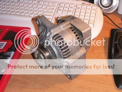
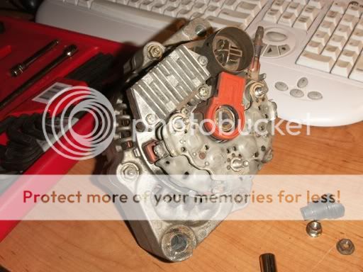
well enough said, here is the pictures (caption below)

4x 1W red leds, mounted to a lightweight aluminum plate, would just fit in this thing without ANY alteration of the original stuff, so it could be reverted when i get that fix it ticket
6 would be just about right for the regulated 14.4v that the alternator puts out, but with 5 , and a bit of resistance, it would be better Balanced, under different voltages , with 4 and a LOT of resistance , i would need fat resisters, and a lot more resistance, but it would be very similar in output at 12-15v even, and more than that it would FIT.

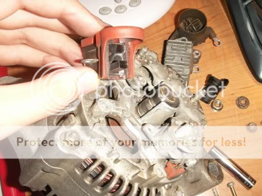
the 194 type connector, was made with a VHS tape tab (hunk of plastic) and copper wires wraped around it, then bonded with j&b weld (not quick)

you can see the wires are stripped far back, so a full 2x wrap goes around the resister, if the resister gets hot enough to melt the solder (it shouldnt if rated proper) the full wrap will insure that it doesnt get sdisconnected.

the resister calculator said about 15-20 ohms and 2 Watts for the resisters, i aquired 6 10ohm 1W resisters, and only used 2. once i tested it IN the car, (before final assembly) i realized the wires leading to the light, and the switch and all reduced the voltage at LOAD enough to only need 5ohms of resistance 2x10ohm parelleled.
with 6 i could make up 5-10-20 if needed.

so there it is done, and heat shrinked, no pics of it in the car.
one thing i didnt think about is WHY there is a rubber seal around the plastic module.
it was so moisture could not get back in there, and FOG up the glass, well it was all fogged up by the time (2am) i got finished, and i ended up Sealing the Fog into the thing (dum dum dum) anyways, i had to open up a edge of the rubber and defog it, then close it up again.
no bridge rectifyer in it, so it must be connected in proper polarity,it ONLY runs when the brake is pressed , so there is not 2 sets of resistance for it.
the 1157 32 led replacements were about as good as a 1157 but not as good as a 2057, which i replace 1157s with usually, so i needed a extra bit of brake jucice to spook the tailgater behind me
you know a HUGE advantage of the leds is they REACT immediatally, instead of in a 30th of a second, they are always talking about what 30th of a second is at 60mph, and if you ask me the DOT should take that into concideration, when they approve of this stuff.
well enough said, here is the pictures (caption below)
4x 1W red leds, mounted to a lightweight aluminum plate, would just fit in this thing without ANY alteration of the original stuff, so it could be reverted when i get that fix it ticket
6 would be just about right for the regulated 14.4v that the alternator puts out, but with 5 , and a bit of resistance, it would be better Balanced, under different voltages , with 4 and a LOT of resistance , i would need fat resisters, and a lot more resistance, but it would be very similar in output at 12-15v even, and more than that it would FIT.
the 194 type connector, was made with a VHS tape tab (hunk of plastic) and copper wires wraped around it, then bonded with j&b weld (not quick)
you can see the wires are stripped far back, so a full 2x wrap goes around the resister, if the resister gets hot enough to melt the solder (it shouldnt if rated proper) the full wrap will insure that it doesnt get sdisconnected.
the resister calculator said about 15-20 ohms and 2 Watts for the resisters, i aquired 6 10ohm 1W resisters, and only used 2. once i tested it IN the car, (before final assembly) i realized the wires leading to the light, and the switch and all reduced the voltage at LOAD enough to only need 5ohms of resistance 2x10ohm parelleled.
with 6 i could make up 5-10-20 if needed.
so there it is done, and heat shrinked, no pics of it in the car.
one thing i didnt think about is WHY there is a rubber seal around the plastic module.
it was so moisture could not get back in there, and FOG up the glass, well it was all fogged up by the time (2am) i got finished, and i ended up Sealing the Fog into the thing (dum dum dum) anyways, i had to open up a edge of the rubber and defog it, then close it up again.
no bridge rectifyer in it, so it must be connected in proper polarity,it ONLY runs when the brake is pressed , so there is not 2 sets of resistance for it.
Last edited: