Battery adapter jig

PGP

Newly Enlightened
Joined
Sep 16, 2005
Messages
128
Location
Anaheim
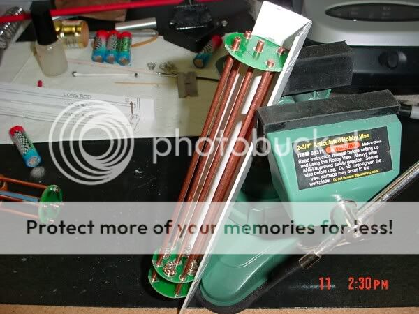
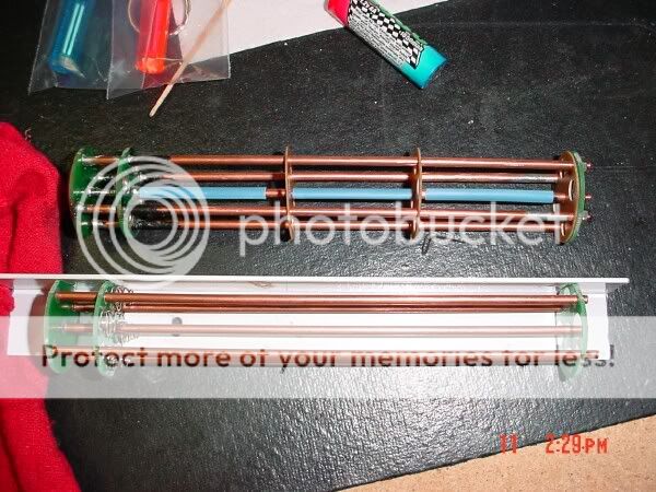
I bought a 12AA-3D adapter kit from Modamag so I could make a battery pack for awr's MAG138 monster. I needed a jig to hold the PCB boards parallel while I soldered the rods to the lower 2 boards. I came up with the idea to use a piece of angle aluminum and cut slots in it to hold the boards. To cut the slots I just used my Dremel hand piece to lay in the V of the angle so each cut was perfectly perpendicular to the angle piece. The Heavy duty cut-off wheel is about the same thickness and diameter as the PCB board. Now I have a jig to make a few of these.

I made an ACAD drawing of the adapter first to figure out what distance all the boards needed to be at. I then printed it out, cut out the PCB boards on the paper and laid it on the angle and marked the angle with a sharpie. Now I know where to make my cuts! The same can be done for all the battery adapter sizes. This particular one I made is just for the MAG138 because the springs had to be removed and the top PCB board is bolted down to the top of the batteries just how awr specified.

Someone has probably already done this, but I have never seen it posted anywhere. If the links dont work then just go here then to my photos/battery adapter jig.

Thanks to Modamag & awr I probaly would have never tried to solder my own battery adapter together & got me thinking on how to make it work!
 
Last edited:

andrewwynn

Flashlight Enthusiast
Joined
Apr 28, 2004
Messages
3,763
Location
Racine, WI USA
PGP sent me the pics after doing this.. man it's really nice.. much more economical than the fancy CNC model that MM uses.. I will be making a very simlier design before i start mass-assembling battery adapters.. maybe i will come up with some 'cheat' to make it adustable and easier to fabricate.. like nesting some angle vs cutting the slots.. or cutting the slots, but directly from the back or something.

Great job, way to be prepared!

-awr
 

TomBrown

Newly Enlightened
Joined
Jun 18, 2005
Messages
153
Location
Regina, SK
Fantastic.

Aluminum cut's beautifully with carbide tipped wood cutting tools. That would be easy to cut on the table saw using the mitre slide.

1/8" kerf would be too much but 3/32" kerf might be pretty close.

Great idea. Thank you. :)

I have a couple of packs to assemble and I was wondering how I'd get it precise. :)
 

andrewwynn

Flashlight Enthusiast
Joined
Apr 28, 2004
Messages
3,763
Location
Racine, WI USA
I have a horiz/vertical metal bandsaw.. hoping i could cut slots from the back side.. or i'll cut bigger n smaller angles to make something.. great design though.

-awr
 

PGP

Newly Enlightened
Joined
Sep 16, 2005
Messages
128
Location
Anaheim
The only reason I did not cut one straight slot from the rear was that the aluminum angle I used was not very thick and I was afraid that it would be flimsy if it did not have 3 attchment points still intact. The 2 spots at each end and the one in the middle. You can try & experiment with diffirent thicknes. You could also glue, JB weld or solder something to the bottom of the V on the outside to help hold it together after you make the full slot cuts.

Patrick
 

modamag

Flashlight Enthusiast
Joined
Aug 16, 2004
Messages
2,101
Location
Bay Area, CA
Great job Patrick :twothumbs:
It always amaze me the ingenuity and things that you all come up with.
 

andrewwynn

Flashlight Enthusiast
Joined
Apr 28, 2004
Messages
3,763
Location
Racine, WI USA
you can also just put another angle behind the cut one. Great to get the back n forth ideas!

I haven't been able to load the images from your site btw.

-awr
 

PGP

Newly Enlightened
Joined
Sep 16, 2005
Messages
128
Location
Anaheim
andrewwynn said:
you can also just put another angle behind the cut one. Great to get the back n forth ideas!

I haven't been able to load the images from your site btw.

-awr

Sorry about that I will try something else!
 

PGP

Newly Enlightened
Joined
Sep 16, 2005
Messages
128
Location
Anaheim
The links should work now, I hope. My Yahoo briefcase is always a crap shoot whether it will work or not. This time I posted them in my yahoo photos. Sorry about the inconvenience!

Patrick
 

PGP

Newly Enlightened
Joined
Sep 16, 2005
Messages
128
Location
Anaheim
I think I finally got the picture thing down!

Here is the ACAD template!
DSC01520.jpg


Here is how I cut the slots!
DSC01546.jpg


Here is how the PCB boards line up!
DSC01525.jpg

DSC01526.jpg

DSC01535.jpg

DSC01534.jpg


Patrick
 

andrewwynn

Flashlight Enthusiast
Joined
Apr 28, 2004
Messages
3,763
Location
Racine, WI USA
I will mention.. there is a serious risk of shorting battery bottoms with the 'hill' of solder that forms a filet at the base of the rods against the PCB.. you can grind away the excess with a dremel, or you can make a taller solder-bump contact (i make a bump of solder and quickly set a broken old battery down to make the contact flat (if you leave it round it will make a helacious dent in the bottom of your cells).

I also wrapped cellophane tape around the rods... 3/8" is perfect, so splitting a 3/4 tape the long way in half works great.

One nice thing with the modded adapter.. you can choose to use the retaining circles or not.

If you have a completed holder you can still mod it.. to take the top off you hold it upside down in a vice and use a butane torch to heat up all 5 rods and pull it off with a pliers.. be verrry careful.. lots of hot solder will drip off!

I use 3mm die to thread now that i have one, no mutzing with the re-tapping 4-40 nuts, and it's a smaller die so it's much easier to deal with turning on a pre-built model.

when putting on the solder bumps on the neg. sides.. you can clean off the solder mask from the trace going to the near rod and decrease resistance more.

nice to see the sharing of info like this!

-awr
 

PGP

Newly Enlightened
Joined
Sep 16, 2005
Messages
128
Location
Anaheim
andrewwynn said:
I will mention.. there is a serious risk of shorting battery bottoms with the 'hill' of solder that forms a filet at the base of the rods against the PCB.. you can grind away the excess with a dremel, or you can make a taller solder-bump contact (i make a bump of solder and quickly set a broken old battery down to make the contact flat (if you leave it round it will make a helacious dent in the bottom of your cells).

I just take a small file & file them down flat! Your way is probably faster!

andrewwynn said:
I use 3mm die to thread now that i have one, no mutzing with the re-tapping 4-40 nuts, and it's a smaller die so it's much easier to deal with turning on a pre-built model.

I still had one of the threads come out crooked so I did all mine with a die holder that has 3 little centering fingers.


andrewwynn said:
when putting on the solder bumps on the neg. sides.. you can clean off the solder mask from the trace going to the near rod and decrease resistance more.

So are you saying that on the back side of the 412 board (the one with the springs) you do not want solder on the trace that goes from the spring to the rod. Oops I added solder on top of the trace thinking that it would allow more current to flow from the batt. neg. to the rod or vice versa.

Patrick
 
Top