I bought a Dorcy super 1 watt. The Led is a LXHL-MW1D. When I put my fluke meter ocross the circuit board, like the led would go I get 5.2 v and 1500ma. On the lumiled's website it states the MW1D led can only handle 350ma max. I would assume I would be safe with a Lux III which is rated 1000ma Max. I dont know what are your thoughts...
You are using an out of date browser. It may not display this or other websites correctly.
You should upgrade or use an alternative browser.
You should upgrade or use an alternative browser.
Luxeon question
- Thread starter DanPar
- Start date

idleprocess
Flashaholic
Current must be measured in series with the load. Measuring it in parallel will give you strange yet meaningless results.
I'm not sure why you're getting 5.2V. The 3xAAA pack should generate ~4.5V open-circuit voltage when the cells are new.
I'm not sure why you're getting 5.2V. The 3xAAA pack should generate ~4.5V open-circuit voltage when the cells are new.
Handlobraesing
Banned
- Joined
- Feb 14, 2006
- Messages
- 2,724
Measuring with the current meter in parallel can make the meter go 
wasBlinded
Flashlight Enthusiast
So you got a current of 1500 mA in in series with the LED? I didn't think AAA alkaline cells could deliver that kind of current. In any event, since a Luxeon I LED is physically the same as a Luxeon III, it should handle 1500 mA in short bursts. If it were extremely well heat sinked, it could go quite a while at those currents without much deterioration, but I'll bet thermal management on that light isn't so good.
I guess you could see 5.2v across the LED at 1500 mA, but that Vf still seems pretty high.
I guess you could see 5.2v across the LED at 1500 mA, but that Vf still seems pretty high.
Randy Shackleford
Enlightened
Would three lithuim AAA's get that kind of mAh reading?
HarryN
Flashlight Enthusiast
I am not an EE, but I will through out some wild ideas based on what I have read from others who seem to know what they are talking about.
- I think that the dorcy board might be a boost circuit, so it is trying to increase voltage to what ever is required to meet the needs of your LED and meter. This could affect the readings.
- Many of the current regulation boards operate in a pulse mode. The average voltage and current might be correct for the LED, but the pulse is quite a bit higher. My own DMM cannot measure this correctly.
- Some lights (not sure about the dorcy ) have 2 frequencies going on to regulate the light - the primary pulses to drive the inductor, and a secondary modulator to pulse width modulate the overall output.
FirstDsent
Enlightened
I am your amatuer electronics guy. I can't find any threads or posts describing the correct way to measure most of the common measurements. In practical terms, how does one measure current in series vs. parallel? How do I make sure I'm measuring the Vf of an LED?DanPar said:I measured the current in series. Im not your amatuer electronics guy. I do Avionics for a living. Its just got these weird reading.
Any advice will be appreciated
Bernie
FirstDsent said:I am your amatuer electronics guy. I can't find any threads or posts describing the correct way to measure most of the common measurements. In practical terms, how does one measure current in series vs. parallel? How do I make sure I'm measuring the Vf of an LED?
Any advice will be appreciated
Bernie
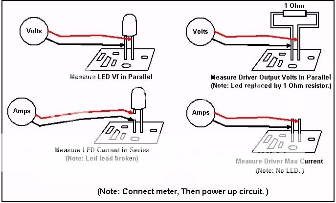
Here ya go Bernie.... Volts are always measured in Parallel, Current is measured in series. "Current in parallel" is meaningless.
greenLED
Flashaholic
:kewlpics: flashlife! Figuring out how to do that was one of the first things I had trouble with when I started modding. A couple of people came to my rescue and I finally figured it out, but your pic speaks 1000 words. I might add that you'll need alligator clips (or some other type of attachment) to secure the DMM leads onto the LED's legs (or wherever you're opening the circuit to measure the current.
There seems to be a bit of confusion as to which Dorcy light he has. [Some posters mention 3AAA's and others mention boost circuit.]
He stated that its a Dorcy Super 1 Watt. Well Dorcy makes 3 models of 1 watters that uses that term, the 3-D, the 2-AA, and the 1-CR123 models.
I am guessing it's the CR123 model, since you mentioned the circuit board. [IIRC, the 3D only has a resistor?] and the 2AA isn't readily available in the states.
If this is correct, HarryN sounds to be on the $$ about the wild readings.
The Pulse wave forms could provide weird readings and the boost circuit at times provide high VDC readings under various loads.
Hope this helps,
Danno
ps I, too, am your amatuer electronics guy
Many 4-digit DMM have too short a sampling time for fly-backs under 50KHz - a 3-10uF capacitor (12v or higher) across the leads will smooth out the readings to give a true average.danielo_d said:The Pulse wave forms could provide weird readings and the boost circuit at times provide high VDC readings under various loads.
FirstDsent
Enlightened
Wow, that is tremendous Flashlife! I had no idea about the difference between series and parallel in this application. I especially had no Idea I would have to break the circuit to measure current to the LED. That you would take the time to draw these is awesome. I can only visualize to the extent that someone is good at explaining. The pictures make it perfectly clear.
Two additional questions though:
1. When measuring driver voltage, is the resistor there to "simulate load"? If not, why?
2. When measuring LED current, should I always use the positive lead, or does it matter?
Thank you,
Bernie
Novice, but creative modder
Two additional questions though:
1. When measuring driver voltage, is the resistor there to "simulate load"? If not, why?
2. When measuring LED current, should I always use the positive lead, or does it matter?
Thank you,
Bernie
Novice, but creative modder
Last edited:
FirstDsent said:...
Two additional questions though:
1. When measuring driver voltage, is the resistor there to "simulate load"? If not, why?
2. When measuring LED current, should I always use the positive lead, or does it matter?
Thank you,
Bernie
Novice, but creative modder
1. Driver voltage should be measured using the setup for measuring Vf, but with the LED replaced by a 1 Ohm resistor to simulate the LED load. One Ohm is the dynamic resistance of most white Luxeons, and since resistors have no Vf you'll be measuring the driver output voltage...not just the Vf of the LED.
EDIT: CPFer "Builder" is right...for VF and Driver Output Voltage measurements you may need a 5-10 microfarad capacitor across the meter to smoothe out the PWM pulses from the driver.
2. Either leg of the LED may be used. If you break the positive LED lead, hook the meter + lead to the circuit, and - to the LED. If you break the LED negative lead, hook meter + to LED and - to the circuit board.
If the meter is digital it will just read the current as 'negative' if you hook it up backwards. If the meter is analog, though the needle may fly backwards if you have it hooked up backwards and the current is high. This can damage or bend the meter needle.
Last edited:
FirstDsent
Enlightened
Thanks again dude!
Bernie
Bernie
The more I use the Dorcy The more I like it. Its a great light. The version I got was with a single cr123a battery. I orderd a lux III star. well see what happens. Althought I do advanced avionics I am clueless on the luxeon star stuff.
It is well beyond the scope of this site for any details, but, here is a penny guide:DanPar said:After reading thru the posts. How does the pulse circuit work. What it driving it.
Regulating power through a LED using just a resistor is the most simple, but is also the most wasteful: any power not used by the LED is "burned up" in the resistor as heat. This applies to "dynamic resistances", or regulators as well, except the excess power heats up the pass transistor.
To better conserve this power, capacitive and inductive methods are used: power is fed into a capacitor or inductor by an oscillator in pulses and is gradually released to the LED as needed. A feedback system is used to either omit a pulse or to change the length of the pulse (PWM) when the power to the LED is too high. This can be used to limit ("buck") or to increase ("boost") the voltage of the supply.
Google on PWM or "pulse width modulation" and "voltage regulators" for the nitty gritty. You can also check out my website here for a bit more background.
Similar threads
- Replies
- 18
- Views
- 403