3rd_shift
Flashlight Enthusiast
Also see my easier 4D cell K2 Magmodding step by step with a megabyte of pics to show you how
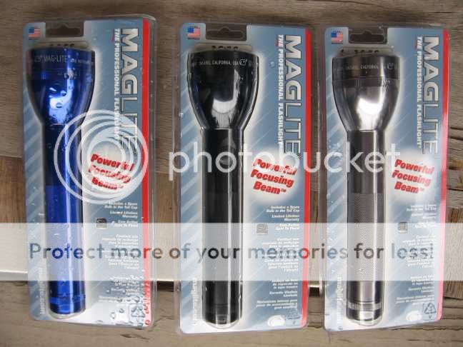
Time to break out the tools again!
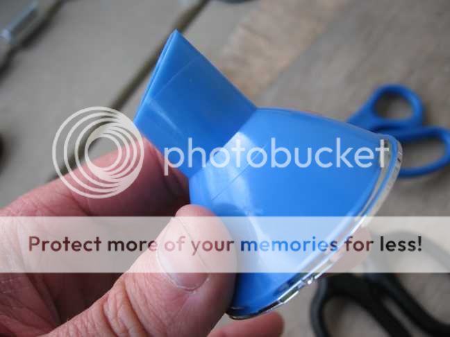
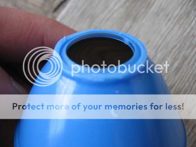
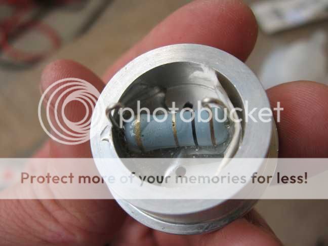
The cam on the reflector needs to go bye-bye.
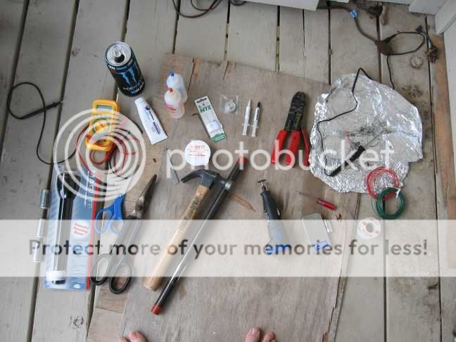
Break out the aviation snips to get started and finish nice and neatly with sharp scissors.
This is important due to the Cree XRE's slightly different focus.
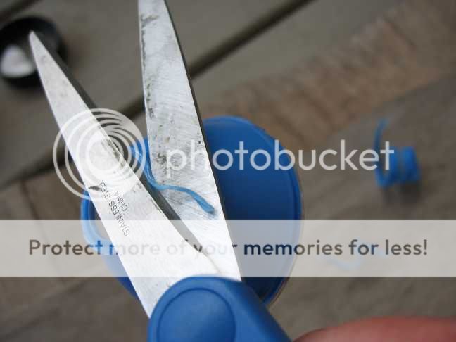
It should end up like this with the cam trimmed all the way down to the apex, or the Cree XRE can't focus to a laser tight spot.
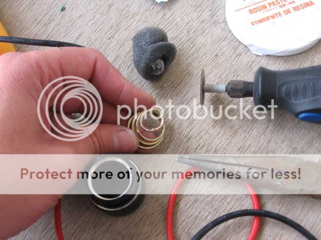
Take off the switch boot without tearing it up.
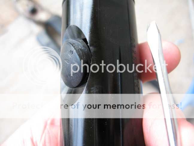
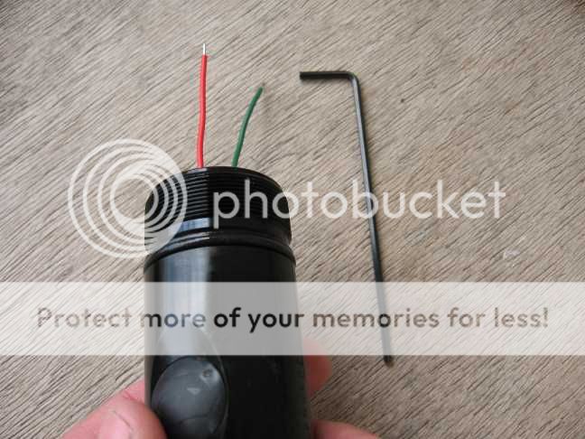
Use a 5/64rths allen wrench to take to loosen the switch assembly like this.
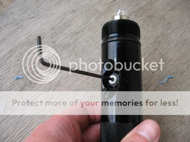
The c cell version will usually fall out freely once loosened.
If not use a chopstick, or something similar to get it out.
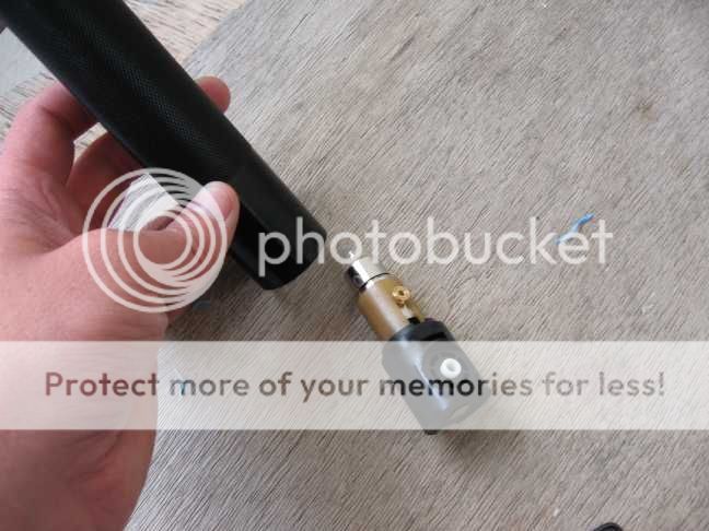
Use that same 5/64rths allen wrench to remove the cam roller from the bulb assembly.
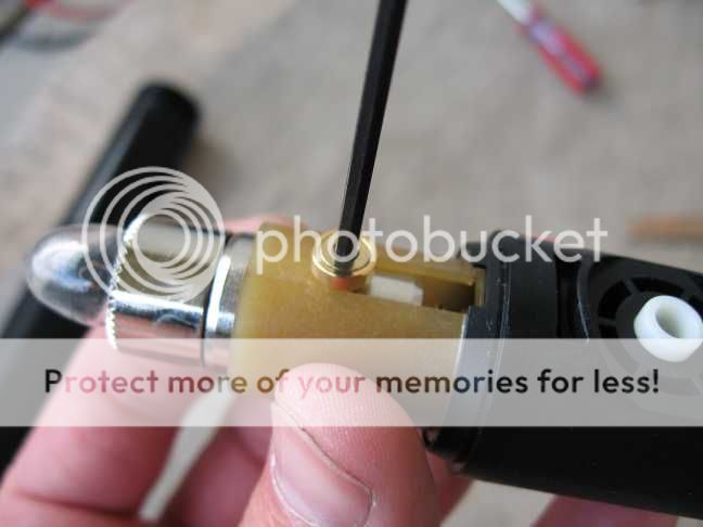
Dump out the bulb holder guts.
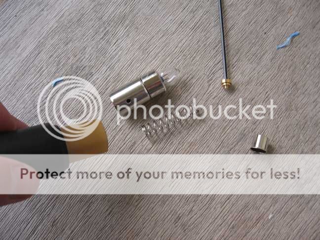
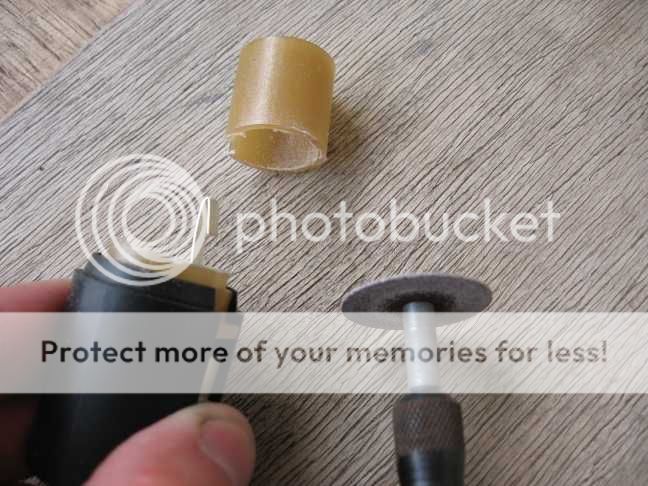
Trim that amber piece of plastic just like so and bend over the (-) tab like this.
That amber piece can be removed all together by opening up the switch assembly,
but then there might be switch parts ending up everywhere and we don't need that for this project.")
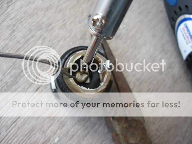
Get a soldering iron and warm it up.
Presolder the (-) tab like this.
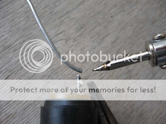
Now get the (+) tab in the center of the switch assembly like this.
A thick blob is fine for soldering the (+) wire into later.
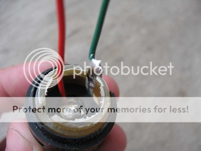
Put the wires in.
The (+) wire needs to be 4-5 inches long.
The (-) should be 3-4 inches in length.
Re-install the wired switch assembly into the flashlight with your 5/64rths allen wrench.
Dang it!
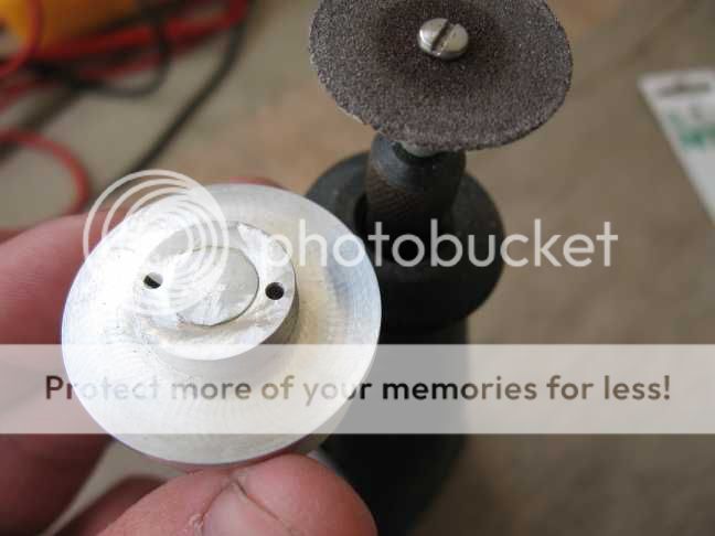
I thought I had a Hotlips heatsink for this and could only find this older Osink.
Those ridges at the top need to go bye-bye. The top MUST be flat!
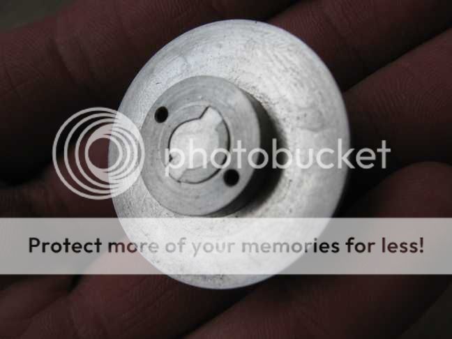
Done!
Make sure whatever heatsink you use is flat like this on top like a hotlips heatsink is.
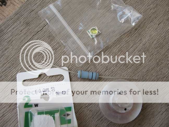
Let's get these parts together.
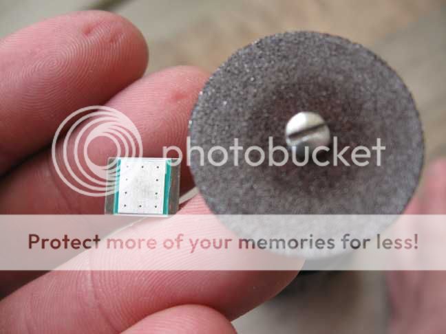
Houston, we have a problem...
Those thin tin strips on the sides underneath need to go bye-bye, or it's short circuit city!

Done!
And do it carefully, or the project may fail right here.
Make your resistor ( a 1 ohm in this case) look something like this.
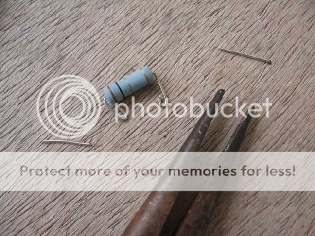
Now look carefully, this is another place where the project can easily end in failure.
The (-) input is closest to the heatsink.
The (-) out to the led is farthest from the heatsink.
Don't let this one short to the heatsink, or flashlight body.
Use as much adhesive as you must to get it to stay put without blocking the heatsink's wire holes.
Regular 2 part epoxy was used in this case.
WARNING! This step may try your patience!
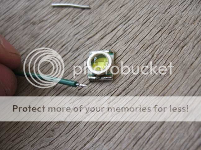
Do the (-) side 1st.
It's the long unbroken strip on the led.
The 2 part strips on the other side of the lense are each (+)
One of those are done later on in this tutorial.
Pre-flux and then presolder the led solder strips and the wires to be soldered to them FIRST!
By the way.. a 25 watt soldering iron is the minimum for this.
This was where I threw my new, smaller soldering iron off the balcony and switched back to my stronger old one. LOL!
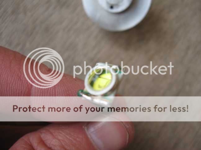
Ok, there's the (-) wire. Again, the long single strip on the led is the led's (-).
Keep the wire and it's solder away from the lense retaining ring to avoid a possible short circuit.
A half millimeter gap will suffice for now.
We will get the (+) wire later.
Mix up some arctic alumina and coat the whole underside of the led.
Even where the tin strips were before they were removed, get the whole thing coated!
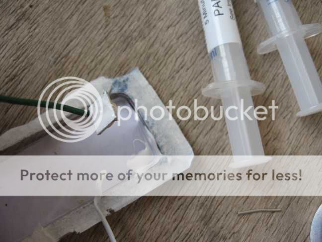
Put the led's (-) wire into either heatsink hole and slide the led down onto the heatsink and "bullseye" center it.
Clean off the excess thermal compound and hold the led firmly and centered onto the heatsink until the adhesive "sets".
Don't let it block the (+) hole in the heatsink.
You will notice that the led nearly centers itself due to the factory placement of the electrodes on it.
Solder the other end of the led's wire to the part of the resistor farthest from the heatsink.
Grab the Maglite and put the (+) wire through the heatsink.
Then solder it's (-) wire to the side of the resistor closest to the heatsink.
Now strip off some insulation from the (+) wire and leave about 2-3 millimeters exposed.
Bend that over into an "L" shape and pull it down onto the (+) side of the led.
Pre-flux and presolder wire and led(+) soldering pad.
Then smash the wire down onto the led's solder pad until ot melts right on there good.
Make sure there is no solder within a half millimeter of the lense retaining ring.
Alright. "deep breath"
Leave the tailcap off and load in some batteries.
Try it out with an ampmeter.
710 milliamps should be no problem for this led with all that aluminum attached to it.
It's... ALIVE!!
Now we can start making messes here.
Apply some thermal grease to the heatsink.
Bend the wires a little and push the heatsink into the light.
Mine went all the way in with a firm hand push this time.
See how some of the white heatsink grease squooshed out? Perfect.
A malot and a short piece of plastic pipe can be used to make yours go in the rest of the way if need-be.
Ok, Now we are going to tackle the issue of wires being too close to the lense retaining ring.
There needs to be at least a quarter millimeter, or more of "gap" between the wires with thier solder, and the lense retaining ring.
Mix up a few drops of regular 2 part epoxy and put some on here like this.
Then get the other side the same way.
Let the adhesive set.
I also took a quarter inch off the tailspring to keep it from squashing the batteries quite so hard.
Load the batteries, tailcap and head.
With the finished flashlight together and working, it's time for some fun.
Here it is at 710 milliamps (left) versus a UWOJ bin Luxeon3 at 1100 milliamps on the right.
Same lights in the living room.

Same lights against a wall.

Heads removed.
Cree XRE on the right this time.
Heads back on aiming up against a white wall.
Cree XRE on the right again.

This project is not for the faint of heart as you can see.
Beginners should do a Luxeon, or K2 mod 1st and get good at that before trying something like this.
Happy modding!!!
Time to break out the tools again!
The cam on the reflector needs to go bye-bye.
Break out the aviation snips to get started and finish nice and neatly with sharp scissors.
This is important due to the Cree XRE's slightly different focus.
It should end up like this with the cam trimmed all the way down to the apex, or the Cree XRE can't focus to a laser tight spot.
Take off the switch boot without tearing it up.
Use a 5/64rths allen wrench to take to loosen the switch assembly like this.
The c cell version will usually fall out freely once loosened.
If not use a chopstick, or something similar to get it out.
Use that same 5/64rths allen wrench to remove the cam roller from the bulb assembly.
Dump out the bulb holder guts.
Trim that amber piece of plastic just like so and bend over the (-) tab like this.
That amber piece can be removed all together by opening up the switch assembly,
but then there might be switch parts ending up everywhere and we don't need that for this project.
Get a soldering iron and warm it up.
Presolder the (-) tab like this.
Now get the (+) tab in the center of the switch assembly like this.
A thick blob is fine for soldering the (+) wire into later.
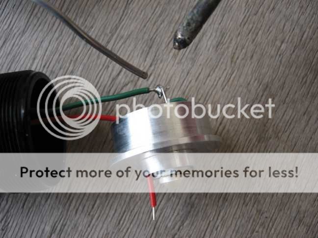
Put the wires in.
The (+) wire needs to be 4-5 inches long.
The (-) should be 3-4 inches in length.
Re-install the wired switch assembly into the flashlight with your 5/64rths allen wrench.
Dang it!
I thought I had a Hotlips heatsink for this and could only find this older Osink.
Those ridges at the top need to go bye-bye. The top MUST be flat!
Done!
Make sure whatever heatsink you use is flat like this on top like a hotlips heatsink is.
Let's get these parts together.
Houston, we have a problem...
Those thin tin strips on the sides underneath need to go bye-bye, or it's short circuit city!
Done!
And do it carefully, or the project may fail right here.
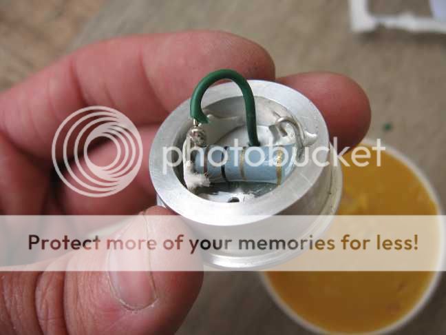
Make your resistor ( a 1 ohm in this case) look something like this.
Now look carefully, this is another place where the project can easily end in failure.
The (-) input is closest to the heatsink.
The (-) out to the led is farthest from the heatsink.
Don't let this one short to the heatsink, or flashlight body.
Use as much adhesive as you must to get it to stay put without blocking the heatsink's wire holes.
Regular 2 part epoxy was used in this case.
WARNING! This step may try your patience!
Do the (-) side 1st.
It's the long unbroken strip on the led.
The 2 part strips on the other side of the lense are each (+)
One of those are done later on in this tutorial.
Pre-flux and then presolder the led solder strips and the wires to be soldered to them FIRST!
By the way.. a 25 watt soldering iron is the minimum for this.
This was where I threw my new, smaller soldering iron off the balcony and switched back to my stronger old one. LOL!
Ok, there's the (-) wire. Again, the long single strip on the led is the led's (-).
Keep the wire and it's solder away from the lense retaining ring to avoid a possible short circuit.
A half millimeter gap will suffice for now.
We will get the (+) wire later.
Mix up some arctic alumina and coat the whole underside of the led.
Even where the tin strips were before they were removed, get the whole thing coated!
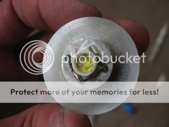
Put the led's (-) wire into either heatsink hole and slide the led down onto the heatsink and "bullseye" center it.
Clean off the excess thermal compound and hold the led firmly and centered onto the heatsink until the adhesive "sets".
Don't let it block the (+) hole in the heatsink.
You will notice that the led nearly centers itself due to the factory placement of the electrodes on it.
Solder the other end of the led's wire to the part of the resistor farthest from the heatsink.
Grab the Maglite and put the (+) wire through the heatsink.
Then solder it's (-) wire to the side of the resistor closest to the heatsink.
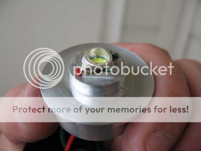
Now strip off some insulation from the (+) wire and leave about 2-3 millimeters exposed.
Bend that over into an "L" shape and pull it down onto the (+) side of the led.
Pre-flux and presolder wire and led(+) soldering pad.
Then smash the wire down onto the led's solder pad until ot melts right on there good.
Make sure there is no solder within a half millimeter of the lense retaining ring.
Alright. "deep breath"
Leave the tailcap off and load in some batteries.
Try it out with an ampmeter.
710 milliamps should be no problem for this led with all that aluminum attached to it.
It's... ALIVE!!
Now we can start making messes here.
Apply some thermal grease to the heatsink.
Bend the wires a little and push the heatsink into the light.
Mine went all the way in with a firm hand push this time.
See how some of the white heatsink grease squooshed out? Perfect.
A malot and a short piece of plastic pipe can be used to make yours go in the rest of the way if need-be.
Ok, Now we are going to tackle the issue of wires being too close to the lense retaining ring.
There needs to be at least a quarter millimeter, or more of "gap" between the wires with thier solder, and the lense retaining ring.
Mix up a few drops of regular 2 part epoxy and put some on here like this.
Then get the other side the same way.
Let the adhesive set.
I also took a quarter inch off the tailspring to keep it from squashing the batteries quite so hard.
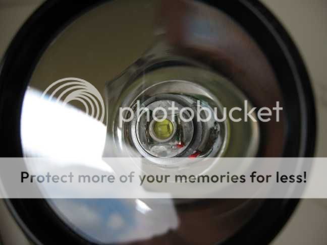
Load the batteries, tailcap and head.
With the finished flashlight together and working, it's time for some fun.
Here it is at 710 milliamps (left) versus a UWOJ bin Luxeon3 at 1100 milliamps on the right.
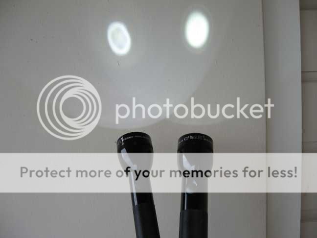
Same lights in the living room.
Same lights against a wall.
Heads removed.
Cree XRE on the right this time.
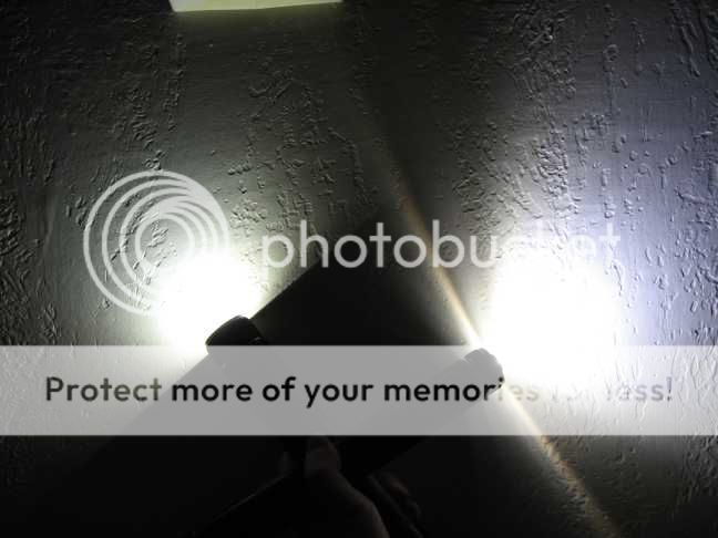
Heads back on aiming up against a white wall.
Cree XRE on the right again.
This project is not for the faint of heart as you can see.
Beginners should do a Luxeon, or K2 mod 1st and get good at that before trying something like this.
Happy modding!!!
Last edited: