Calina said:
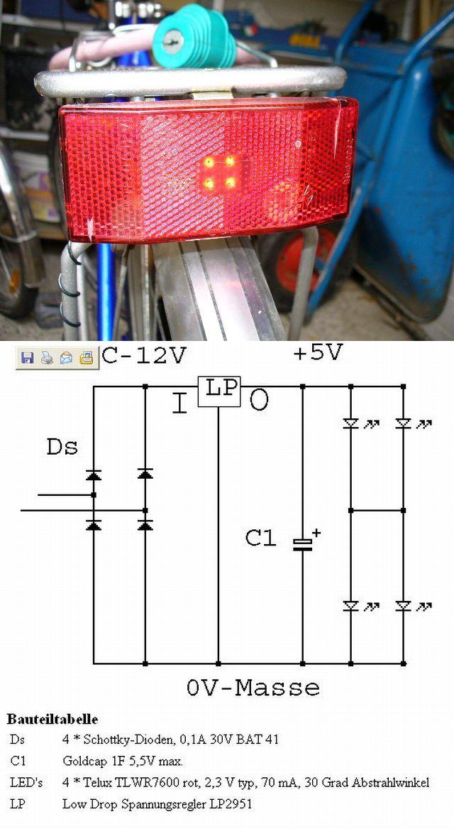
Dynamo are AC devices.
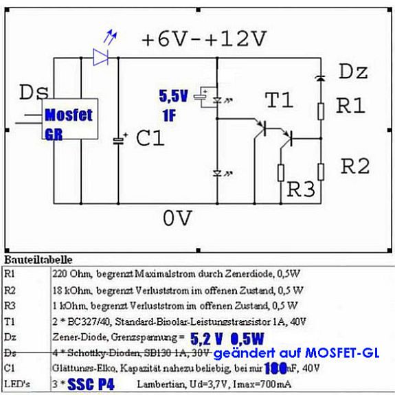
Your set up works but I think there is a danger of harming the LED with reverse current if you don't have at least a zener diode in the circuit. Also with a direct drive set up, you are only using half of the power available and as such generate only half of the light you could get. The bridge gives you access to all the power and the light would not flicker. If you add a capacitor the light level should be very constant.
What dynamo and light do you use? How is you light beam (considering it is only half of what it could be)? What optics do you have? How do you use the light (city roads or dark trails, be seen or lighting up the road, commuting on a regular basis or occasional use only or ...)?
I'm not sure why they don't make DC generators. My guess is that this would imply a more complex design (brushes etc.) that would be more expensive and not as reliable.
With two LEDs you could use one phase for each light and not even use a bridge (just put a couple of zeners to prevent reverse current damage). Your lights will still ficker at low speed though.
Let me had that I'm no expert on the subject but I tried a few things, read a lot about it and did managed to learn a little.
hi and thanks to everyone for the advice. feeling a little "in over my head" at the moment, im not great with circuit diagrams. i see now why i need to use at least a bridge rectifier, basically to convert the negative portion of the wave to positive right?
so can you just buy a bridge rectifyer? where? im pretty clueless so if you can recommed one, that would rock :rock: its a 6V 3W dynamo light system made by schwinn, sold for $10 at target. i dont plan on using the lights it came with.
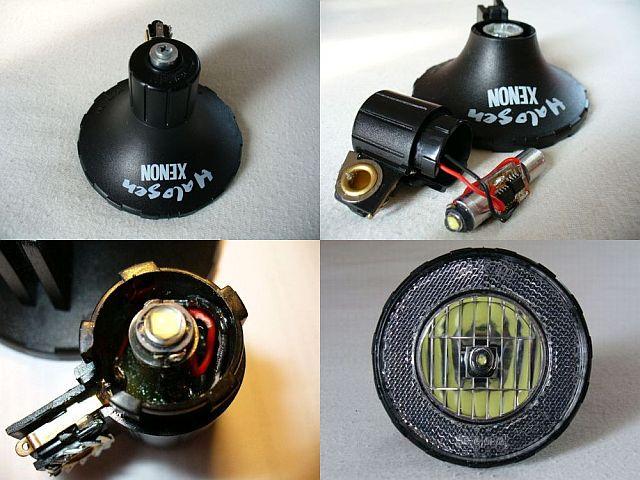
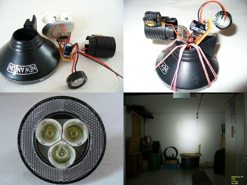
i actually havent tried the led with the dynamo, but i thought it would be similar to my DC Hand crank light W/seoul p4. (obviously i was wrong). its a simple $5 hand crank 3led light, i removed everything but the DC motor, gears, and crank and wired it directly to the Seoul P4. Wow. the seoul needs a big heatsink. got 700ma when cranking moderately, 850 when cranking fast. the voltage stays in accordance with the current, between 3.5v and 3.9v. when the led is disconnected, it reads more like 15v. i used a teeny tiny plastic reflector super-glued right onto the star and its perfect for about 45degrees of smooth flood. too bad i cant convert this little generator for my bike, so so simple. at least i have a nice 100+ lumens crank light for emergencies!
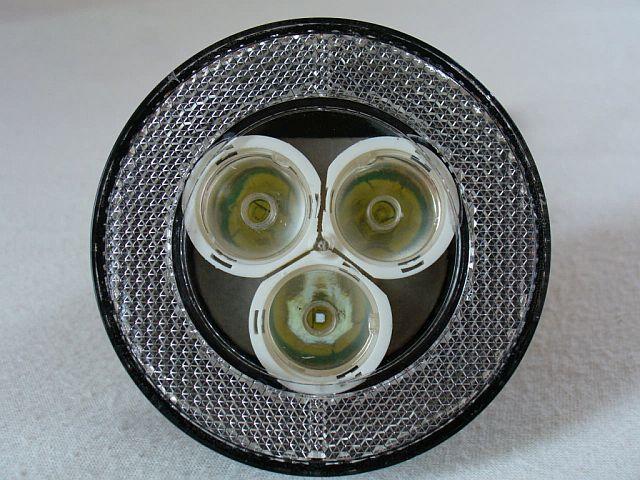
my end setup will hopefully be something like: 2-3 cree P4s bare for close up flood light, each running about 600-800ma on a decent heatsink, powered by the dynamo. also, a 3 cree throw light on the handlebars (like Nightrider's awesome creation) , probably powered 18650 by batteries. im currently too cheap/inexperienced to try to regulate either light with a driver. my commute is 20 minutes so runtime barely matters. dont have much acess to dark trails

My IDEAL setup is much different, however. I want a truly HYBRID bike light system, one that runs on batteries that are recharged by the dynamo. like a good hybrid car, the dynamo should only engage when the brakes are engaged. part of my commute is down a steep hill for like a mile. breaks are engaged the whole way down, wasting energy. on the way home, its uphill, and id rather not have extra drag from a dynamo then (btw, how much drag can they cause?) im thinking if i were to replace my front break-pads with dynamos, that would technically work, but then id only have rear breaks. i kinda doubt anyone makes a dynamo that could really make use of all that kinetic energy tho. there are alot of red lights to stop for where i ride, would be cool if every time i stopped, my kinetic energy were stored in the battery!
ok just had an idea: if the load is huge it would slow me down right? just connect the load instead of engaging the breaks... i know when i connect the seoul to my hand crank it become way harder to crank. same with dynamo?
im sorry this post is huge. thank you for getting all the way thru it!