
Nereus
Enlightened
I finished some time ago my second 2D magseoul mod. The specs of the mod are:
- Bored out mag 2D
- 2D to 8 AA battery holder
- UCL lense
- 4*Seoul P4 U-bin leds
- 4*McR20s reflectors
- Modified Modamag's PES2-D heatsink
- Shark 30/200/900 mA converter
- Self-made 3-stage control circuit for the Shark
- Runtimes 50 / 10 / 2 hours correspondingly (estimates for 2700 mAh nimhs)
The control circuit (see here) that I made makes separate control switch un-necessary. Instead, the brightness levels will be controlled with the original mag switch by turning the flashlight on and off:
*Turn the flashlight on -> it starts on low level.
*Turn the flashlight off and quickly on -> mid level.
*Turn the flashlight off and quickly on again -> high level.
*Turning the flashlight off and on one more time will start the sequence from the beginning (low).
* Keeping the flashlight off for more than 3 seconds in any stage of the sequence will zero the circuit and start the sequence from the beginning.
So, this is where the modding starts:
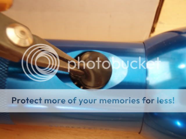
Remove the switch cover:
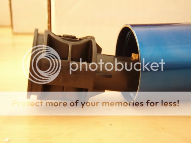
Unscrew the head:
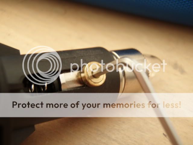
Loosen the screw holding the switch with a hex wrench:
Push the switch holder out:
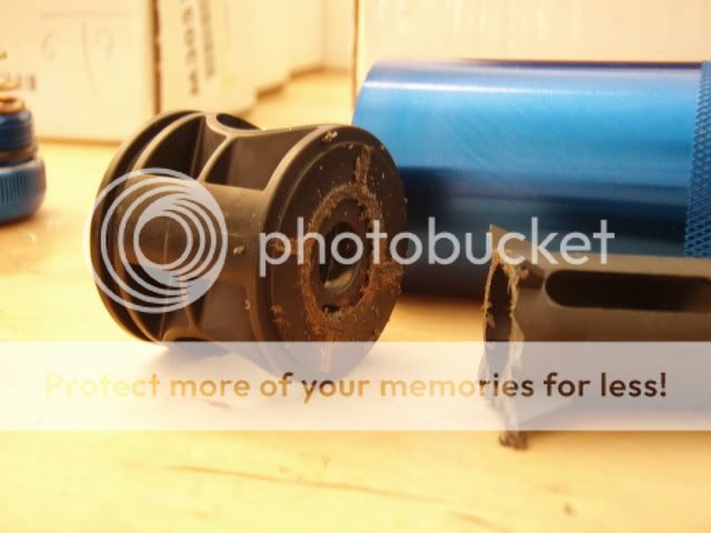
Remove the metallic bulb holder:
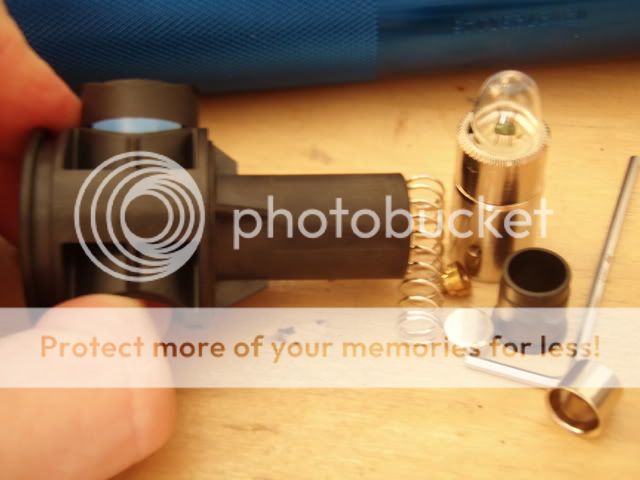
Push the switch out of the switch holder:
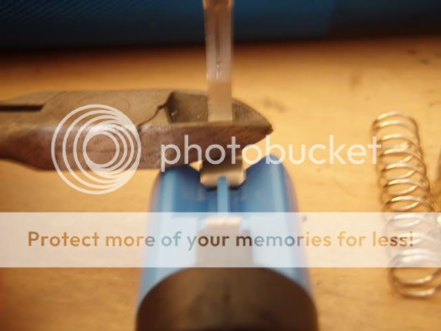
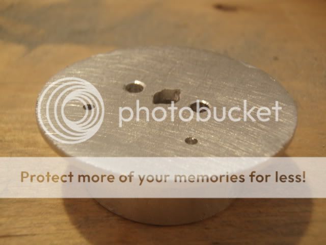
Cut the minus contact lead:
Cut the plastic bulb holder:
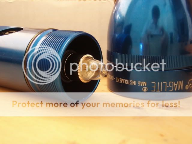
Remove the battery holder retaining ring inside the tube:
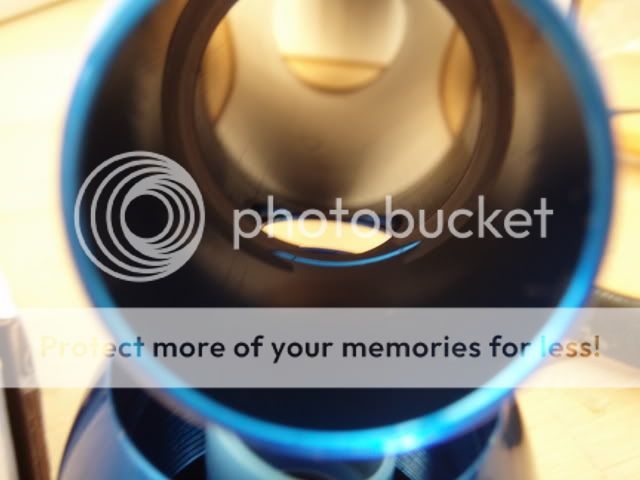
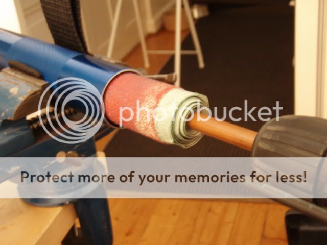
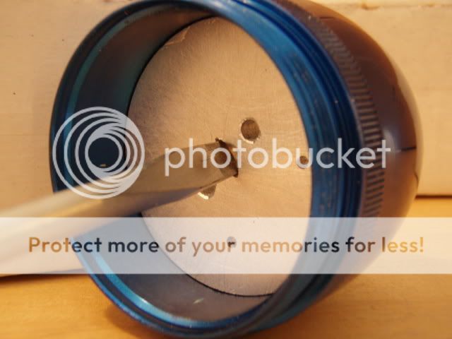
Bore out the battery tube so that its inner diameter increases by 1mm. I don't have a lathe so I used sanding paper and drill like shown below... boring is boring without lathe! :green:
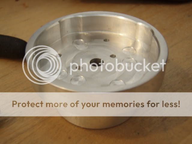
Here you can see non-modified PES2-D heatsink:
I prefer installing leds on a flat surface. That's why I sanded the heatsink edges down. Note also that I have modified the middle hole so that a screwdriver can be used to screw/unscrew the heatsink. This feature will be needed later:
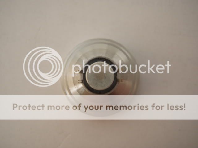
Remove the original lense and reflector and screw the heatsink to its place:
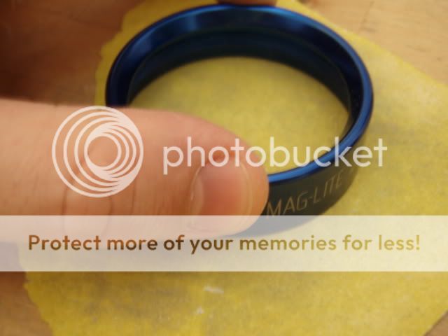
The bezel is a bit too tall. Sand it some 1 mm shorter so that it squeezes the reflectors and leds nicely:
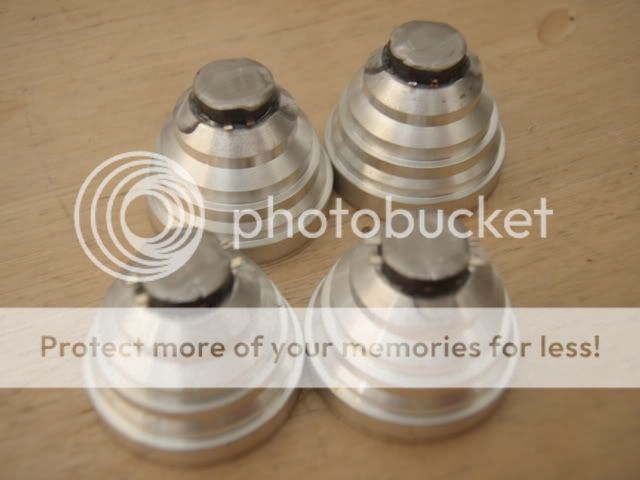
Cut the led leads shorter. Turn the reflector upside down and drop the led to its place. Center the led and when it's properly centered drop few drops of cyanoacrylate glue to both sides of the led. From now on the led+reflector combo will be one non-separable unit. Do this to all four leds and let the glue dry properly:
Apply a thin electrically insulating layer of arctic silver epoxy to the slug of each emitter:
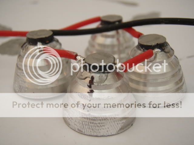
File the reflector sides so that they fit in the mag head. After that, solder the wires to each emitter so that they are connected in series:
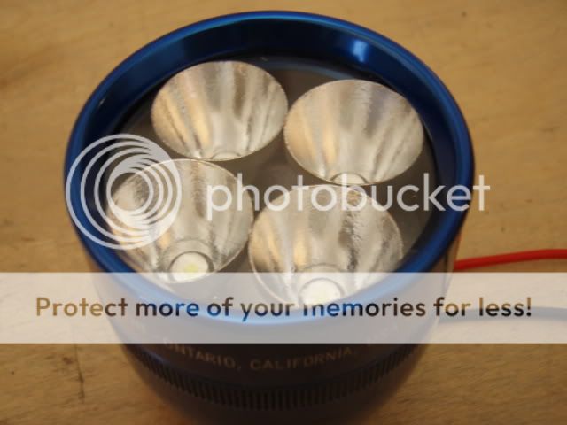
Apply arctic silver epoxy to each slug and drop the led+reflector units to the flashlight head. Use the bezel and lense to squeeze the led+reflector units down:
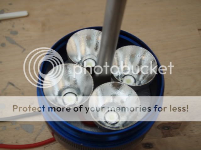
This is why you want to modify the heatsink middle hole: now you can use a screwdriver to unscrew the heatsink+leds+reflectors combo after the arctic silver epoxy has cured:
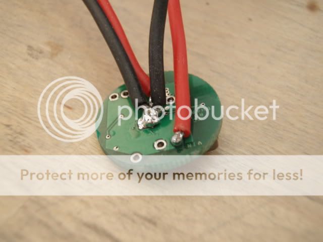
Solder the input and output wires to the back side of the Shark converter:
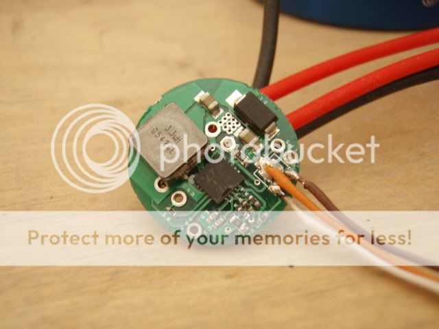
Remove the trimpot and connect three wires to the trimpot contacts:
Use arctic silver to glue the Shark to the back side of the heatsink:
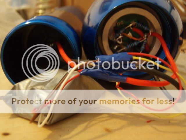
There are two voltage dividers connected to two mosfets. Thin yellow and red wires control which voltage divider (and which brightness level) is active:
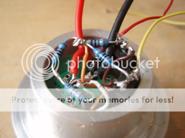
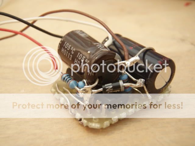
Here is the control circuit that I made for the Shark. It consists of 4017 decade counter and a few auxilary components.
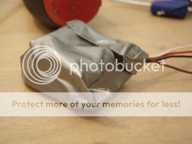
The control circuit needs to be wrapped with duct tape:
Apply arctic silver paste to the threads of the heatsink...
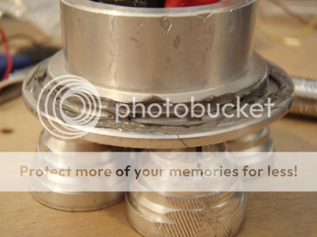
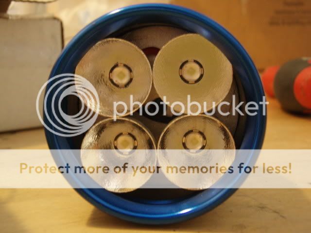
...and install the heatsink, bezel and UCL lense:
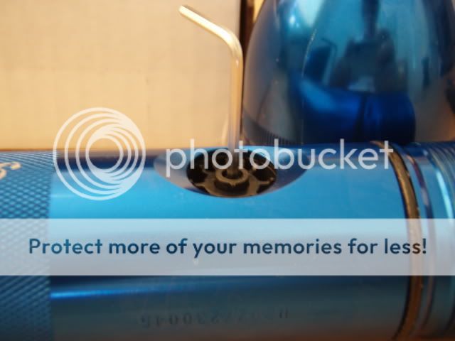
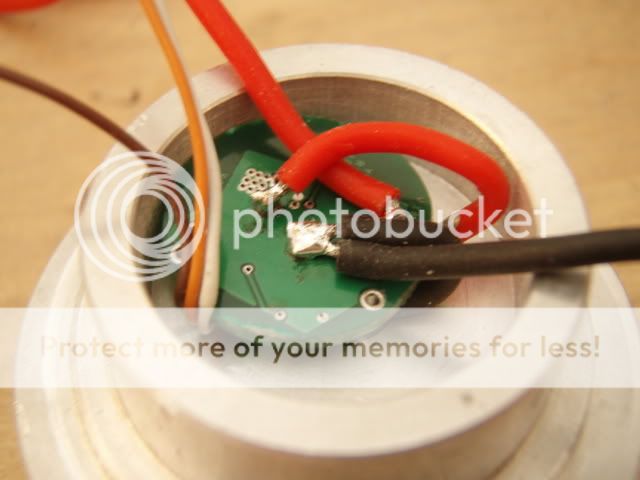
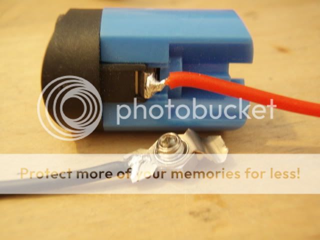
Solder wires to the switch:
Install the switch-holding metal ring to the battery tube and push the switch back to the switch holder:
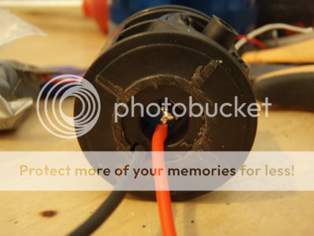
Connect the wires...
...and screw the flashlight head to its place:
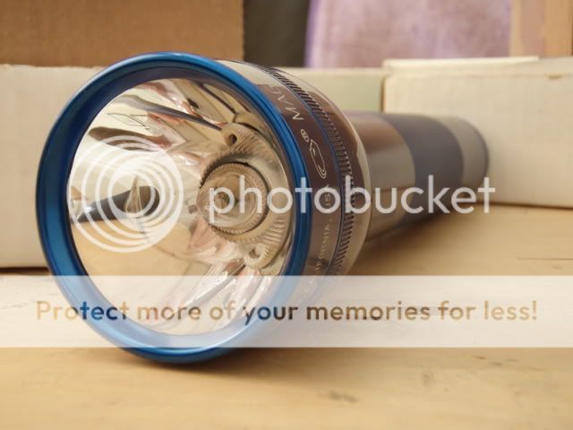
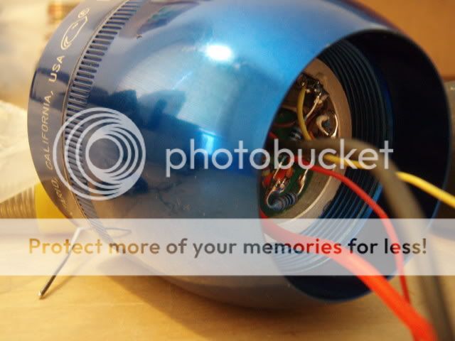
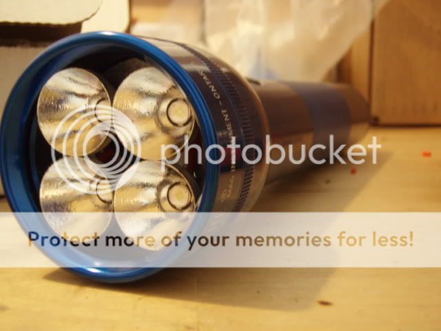
Here is the finished magseoul mod!")
This mod is very close to my first magseoul mod and you can find beamshots in the thread describing it.
Thanks for looking!
-N
- Bored out mag 2D
- 2D to 8 AA battery holder
- UCL lense
- 4*Seoul P4 U-bin leds
- 4*McR20s reflectors
- Modified Modamag's PES2-D heatsink
- Shark 30/200/900 mA converter
- Self-made 3-stage control circuit for the Shark
- Runtimes 50 / 10 / 2 hours correspondingly (estimates for 2700 mAh nimhs)
The control circuit (see here) that I made makes separate control switch un-necessary. Instead, the brightness levels will be controlled with the original mag switch by turning the flashlight on and off:
*Turn the flashlight on -> it starts on low level.
*Turn the flashlight off and quickly on -> mid level.
*Turn the flashlight off and quickly on again -> high level.
*Turning the flashlight off and on one more time will start the sequence from the beginning (low).
* Keeping the flashlight off for more than 3 seconds in any stage of the sequence will zero the circuit and start the sequence from the beginning.
So, this is where the modding starts:
Remove the switch cover:
Unscrew the head:
Loosen the screw holding the switch with a hex wrench:
Push the switch holder out:
Remove the metallic bulb holder:
Push the switch out of the switch holder:
Cut the minus contact lead:
Cut the plastic bulb holder:
Remove the battery holder retaining ring inside the tube:
Bore out the battery tube so that its inner diameter increases by 1mm. I don't have a lathe so I used sanding paper and drill like shown below... boring is boring without lathe! :green:
Here you can see non-modified PES2-D heatsink:
I prefer installing leds on a flat surface. That's why I sanded the heatsink edges down. Note also that I have modified the middle hole so that a screwdriver can be used to screw/unscrew the heatsink. This feature will be needed later:
Remove the original lense and reflector and screw the heatsink to its place:
The bezel is a bit too tall. Sand it some 1 mm shorter so that it squeezes the reflectors and leds nicely:
Cut the led leads shorter. Turn the reflector upside down and drop the led to its place. Center the led and when it's properly centered drop few drops of cyanoacrylate glue to both sides of the led. From now on the led+reflector combo will be one non-separable unit. Do this to all four leds and let the glue dry properly:
Apply a thin electrically insulating layer of arctic silver epoxy to the slug of each emitter:
File the reflector sides so that they fit in the mag head. After that, solder the wires to each emitter so that they are connected in series:
Apply arctic silver epoxy to each slug and drop the led+reflector units to the flashlight head. Use the bezel and lense to squeeze the led+reflector units down:
This is why you want to modify the heatsink middle hole: now you can use a screwdriver to unscrew the heatsink+leds+reflectors combo after the arctic silver epoxy has cured:
Solder the input and output wires to the back side of the Shark converter:
Remove the trimpot and connect three wires to the trimpot contacts:
Use arctic silver to glue the Shark to the back side of the heatsink:
There are two voltage dividers connected to two mosfets. Thin yellow and red wires control which voltage divider (and which brightness level) is active:
Here is the control circuit that I made for the Shark. It consists of 4017 decade counter and a few auxilary components.
The control circuit needs to be wrapped with duct tape:
Apply arctic silver paste to the threads of the heatsink...
...and install the heatsink, bezel and UCL lense:
Solder wires to the switch:
Install the switch-holding metal ring to the battery tube and push the switch back to the switch holder:
Connect the wires...
...and screw the flashlight head to its place:
Here is the finished magseoul mod!
This mod is very close to my first magseoul mod and you can find beamshots in the thread describing it.
Thanks for looking!
-N
Last edited:
