This is how you modify standard mag switch to up to 10-stage switch

Nereus

Enlightened
Joined
Mar 11, 2005
Messages
509
Location
Espoo, Finland, Northern Europe
When I built my second magseoul mod I designed a circuit that transforms standard D mag switch to a 3-stage switch: the brightness levels are controlled with the original mag switch by turning the flashlight on and off:
*Turn the flashlight on -> it starts on low level.
*Turn the flashlight off and quickly on -> mid level.
*Turn the flashlight off and quickly on again -> high level.
*Turning the flashlight off and on one more time will start the sequence from the beginning (low).
* Keeping the flashlight off for more than 3 seconds in any stage of the sequence will zero the circuit and start the sequence from the beginning.

I used 4017 decade counter IC (see useful info here) with a few auxilary components. Here is the schematics of the control circuit:

4017_2.jpg


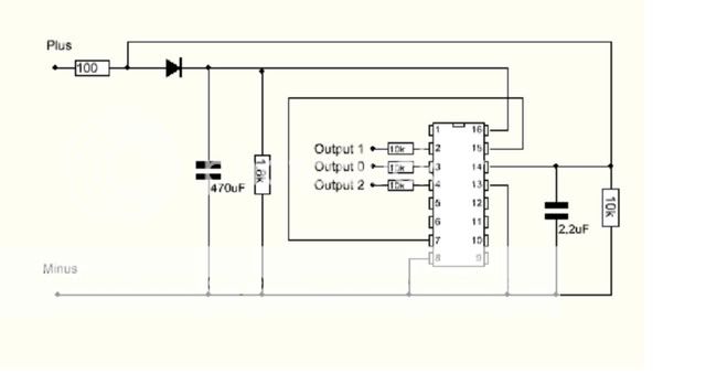
The 4017 decade counter has ten separate outputs (0-9) which go high in sequence when the power to the clock pin (=pin #14) is pulsed. In my circuit I use only three first outputs, 0, 1 and 2. I have connected 3rd output (=pin #7) to the reset (=pin #15). As a result, when the flashlight is turned on for the fourth time, 3rd output pulls the reset pin up and the IC will immediatly start the sequence from the beginning (output pin 0 goes high). There are 10 output pins in 4017 so up to ten brightness levels can be created.

The 470 uF + 1,8 kOhm RC network keeps the IC alive for 3 seconds after turning the power off. Longer off-state will make the IC "forget" its previous on-state and starts the sequence from the beginning. 2,2 uF + 10 kOhm RC network prevents on/off transient voltage spikes from acting as pulses to the clock pin.

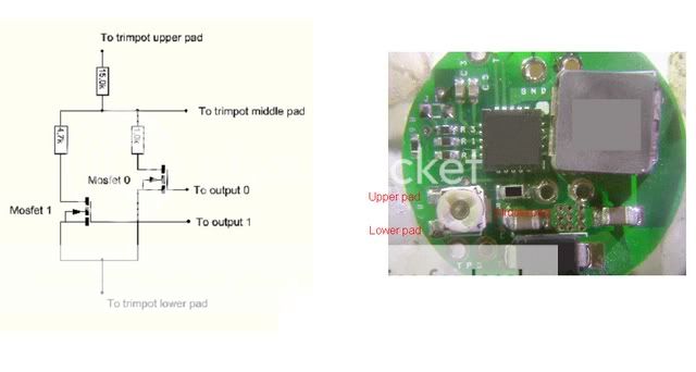
In my magseoul mod I removed the trimpot of the Shark and replaced it with two voltage dividers connected to two n-type mosfets. Then I used this circuit to drive the gates of the mosfets. This is what the circuit looks like:

P5290466.jpg


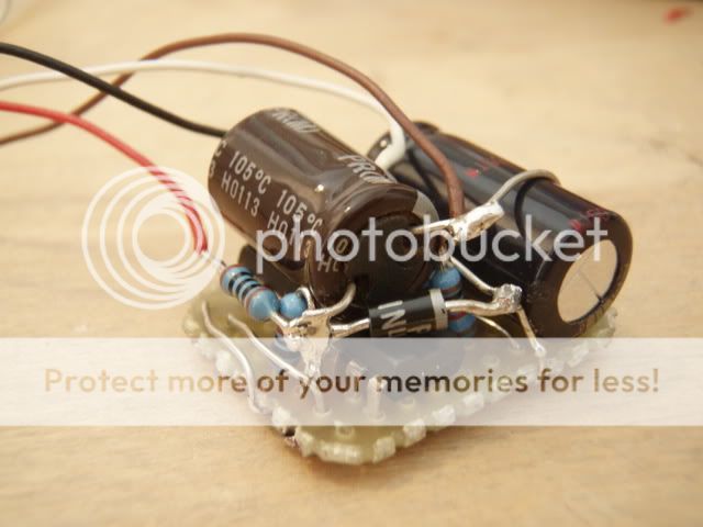
Not very beautiful... but it fits nicely in a Mag D tube and works great! :)

-N
 
Last edited:

Essexman

Flashlight Enthusiast
Joined
Oct 9, 2006
Messages
1,192
Location
U.K.
Thanks Nereus. I'll have to study this in detail later (electronics is not my strong point!).:thinking:
 

joedm

Newly Enlightened
Joined
Jun 13, 2006
Messages
161
Location
Australia
Thanks this is great!!:thumbsup:
My electronics is also rather hit & miss but I'll definitely be giving this a go.

My project in mind will use the AMC7135 circuit from DX and use the counter to bridge the 2 remaining bridges that will enable 700ma & 1050 ma. By default it will have 350ma. I will also add my flashing circuit in there if i can to have that 4th strobe mode. :naughty:

Thanks again.
 

joedm

Newly Enlightened
Joined
Jun 13, 2006
Messages
161
Location
Australia
ok here come my stoopid questions.

What's that diode you're using and does it make a difference? Is it only for wrong polarity safeguard?

Are the values of the capacitors affected by the supply voltage? What is your supply voltage? Is it the same as the supply delivered to your shark circuit (in parallel with the batteries)?

So the outputs go to the gates of the mosfets? but you only have 2 mosfets? where is the 3rd output going? and I can only see 4 wires so +ve, -ve and 2 outputs, so my guess is there is only 2 outputs?

I don't understand how the shark determines what level to drive your leds at however my guess is the resistors determine this and hence the relevant mosfet will supply power through the relevant resistor to the shark.

Thanks again for posting this. As you can see I'm still learning. :thinking:
 

Nereus

Enlightened
Joined
Mar 11, 2005
Messages
509
Location
Espoo, Finland, Northern Europe
What's that diode you're using and does it make a difference? Is it only for wrong polarity safeguard?

The diode allows the clock pin (#14) to go immediatly low when the power is interrupted. Without the diode the 470 uF capacitor would keep it up. It would not be possible to cycle the brightness levels without the diode.

Are the values of the capacitors affected by the supply voltage? What is your supply voltage? Is it the same as the supply delivered to your shark circuit (in parallel with the batteries)?

Yes, the control circuit is connected in parallel with the Shark. Input voltage is somewhere around 10V (8 AA nimhs). I think you should be able to use same capacitance capacitor even though the input voltage was different. Generally, you should be able to change component values and still create a working circuit.

So the outputs go to the gates of the mosfets? but you only have 2 mosfets? where is the 3rd output going? and I can only see 4 wires so +ve, -ve and 2 outputs, so my guess is there is only 2 outputs? I don't understand how the shark determines what level to drive your leds at however my guess is the resistors determine this and hence the relevant mosfet will supply power through the relevant resistor to the shark.

Below you can see schematics that tells you how I connected Shark and the control circuit:

VoltageDivShark.jpg


Shark output current is determined by the voltage at the middle pad of the trimpot. The trimpot acts as a voltage divider and it can be replaced with a voltage divider consisting of ordinary resistors.

When the output 0 is high (low mode) the mosfet 0 and voltage divider consisting of 1,0 kOhm and 15,0 kOhm resistors are active. When the output 1 is high (mid mode) the mosfet 1 and voltage divider consisting of 4,7 kOhm and 15,0 kOhm resistors are active. I'm violating here the recommendation to use 20 kOhm total resistance voltage divider, but who cares since the Shark works nicely like this, too... :)

When the output 2 is high (high mode) outputs 0 and 1 are low. This means that no voltage divider is active: neither of mosfets conducts. This corresponds to a situation that there would be no trimpot at all. In this situation the output current is set by the 0,1 ohm sense resistor (~1A) of Shark. This is why Shark is a kind of a special case: you do not need to connect 2-output anywhere. To create high mode, it is enough that output 0 and 1 are low.

Hope this helps. :)

-N
 

joedm

Newly Enlightened
Joined
Jun 13, 2006
Messages
161
Location
Australia
wow thanks for the in depth reply...

In my case I will be using the AMC7135 1050mA circuit boards from DX. This board consists of 3x AMC7135 which delivers 350ma each. However only 1 AMC7135 is connected on this board.

The circuit will output 350ma by default which I will set as Output 3. Since no bridging of jumpers is required, this will work similar to how you have setup up the shark. However for the other two modes I guess I will require 2 mosfets. Mosfet 0 which will be used to drive high mode (i.e. 1050ma) will have it's gate connected to Output 0 (first mode) and when it conducts will bridge the two jumpers to enable the 2 remaining AMC7135's hence 1050mA. Mosfet 1 will be used for MEDIUM mode (2nd mode) and when it conducts will only bridge 1 of the 2 jumpers hence enabling 700mA.

Do you see any problem with what I am planning to do?
 

snipinglight

Newly Enlightened
Joined
Sep 2, 2006
Messages
168
I'm still learning about electronics.

1) In the schematics diagram, what is the value 100 near the 'plus' ?
2) One end of the 10kohm resistor connects to pin 4 how about the other end?
3) what is the voltage rating of the 470 micro farad capacitor and how about the voltage rating of the 2.2 micro farad capacitor?
4) Is there a value for mosfet?

Thanks
 

gandbag

Newly Enlightened
Joined
Mar 16, 2004
Messages
42
I'm still learning about electronics.

1) In the schematics diagram, what is the value 100 near the 'plus' ?
2) One end of the 10kohm resistor connects to pin 4 how about the other end?
3) what is the voltage rating of the 470 micro farad capacitor and how about the voltage rating of the 2.2 micro farad capacitor?
4) Is there a value for mosfet?

Thanks


1) This appears to be a 100 Ohm resistor
2) This is answered in post #5
 

Robban

Enlightened
Joined
Jul 6, 2004
Messages
849
Location
Sweden
Thanks for posting this. I wont be replicating this circuit but I wasn't quite clear on how to hook up resistors instead of a pot. Hopefully I'll be able to fit what I want to do inside my 2C (that dang thing is cramped...)
 

Nereus

Enlightened
Joined
Mar 11, 2005
Messages
509
Location
Espoo, Finland, Northern Europe
Snipinglight: 1) and 2) has been answered in the post #10. The voltage rating of the 470uF capacitor is 16V, IIRC. The voltage rating of the 2,2uF capacitor is ridiculously high, 350V... I had nothing else available when building the circuit. 16V capacitor should work nicely. I used BUZ11 mosfets - but almost any general n-type mosfet should work.

Jimjones3630: Thanks! :)

-N
 

Jenova

Enlightened
Joined
Oct 22, 2007
Messages
201
anyone had any luck with this

i just tried it and no go tried on a breadboard and now a pcb ???

im using a 6AA to power all contacts are good and no shorts

using all the right resistors and the caps im using are
470uf - 10v
2.2uf - 450v (only one i could find)

on output 0 i get 5.71v
on output 1 and 2 i get nothing after quickly pressing the button

it seems like output 0 stays on all the time
 

Nereus

Enlightened
Joined
Mar 11, 2005
Messages
509
Location
Espoo, Finland, Northern Europe
anyone had any luck with this

i just tried it and no go tried on a breadboard and now a pcb ???

im using a 6AA to power all contacts are good and no shorts

using all the right resistors and the caps im using are
470uf - 10v
2.2uf - 450v (only one i could find)

on output 0 i get 5.71v
on output 1 and 2 i get nothing after quickly pressing the button

it seems like output 0 stays on all the time

6AAs should be ok to power the circuit. Here are couple of ideas that come to my mind:
1) Do you have the diode in the circuit connected like in the schematics? Without it the circuit behaves exactly like you describe.
2) Is the clock pin (#14) getting proper pulses? Try disconnecting it and pulsing the pin directly from the battery + and theck the voltage at output pins.
3) What is the RC constant time of the keep-alive RC network? If that is too low the circuit behaves like you describe. If you are using 470 uF cap, then the question is do you have ~1,8 kOhm resistor.
4) 4017 decade counter is very sensitive to ESD - your IC may be damaged.

-N
 
Last edited:

TheInvader

Newly Enlightened
Joined
Jul 16, 2009
Messages
109
Revive.

How many amps would this circuit drive?
I'm looking to use this as a ghetto soft-start for a 1185 bulb (draws 3.5-4 amps)
 

alpg88

Flashlight Enthusiast
Joined
Apr 19, 2005
Messages
5,336
i got a question,
i'm working on a project where i have to power 6 devices, max device draw is 1,5 amps, i was thinking of few switches, than a rotary switch, but your counter would be the best, i only need 1 switch.
will it handle 1,5 amps, or i,d need to use relays,
drivers and resistors for devices are after this switch.
 
Top