Very simple/cheap dynamo led light

bbaker22

Newly Enlightened
Joined
Oct 28, 2005
Messages
126
Location
Colorado, USA
So, while trying to understand the discussion generated by another thread I started (http://candlepowerforums.com/vb/showthread.php?t=172636), I've put together a simple, cheap, and effective lighting solution for road riding (driven off of a Shimano dynamo hub):

Cree XR-E P4 bin (I have a Q5 that I'll install once I'm happy w/ the setup)
Optic and holder (https://www.kaidomain.com/WEBUI/ProductDetail.aspx?TranID=1603)
Radio Shack rectifier (http://www.radioshack.com/product/i...igkw=rectifier&kw=rectifier&parentPage=search)
Two 3/4" copper end caps
JB weld to join the two caps
Bottle cap to seal the back end
Twofish lockblock

What I like: :thumbsup:
much much brighter than my previous halogen light (prob ~150 lumens w/ Q5)
very small and unobtrusive
lights up immediately (vs my 3 led configuration)
throws light way down the road
ridiculously easy to put together
fairly easy to update emitter

What I don't like: :thumbsdow
no switch (will add to final version)
throws light way down the trail (would rather have flood for off-road use)
not quite waterproof (need to seal holes at edge of optic holder and wire hole on bottle cap)
need to eliminate electrical tape sealing (to expose copper for effective cooling)
not bright enough for fast off-road use

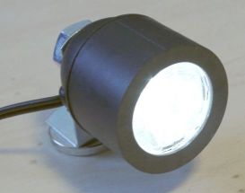
Here are a couple pics...


CreeDynamoLight3small.JPG
CreeDynamoLight3small.jpg


baker
 
Last edited:

alexlockhart

Newly Enlightened
Joined
Jun 27, 2007
Messages
60
I feel partially responsible for getting your previous thread headed in the direction it's going. While it's turning into a truly fascinating discussion that's helpful to my ambitious plans, I suspected we had wandered away from the cheap and simple thing you were after. So I'm glad to hear you went ahead and built your light.

It looks pretty nice, and I like your choice of components. (I also like your choice of bike - I just built up a LHT!) My plans are to use the 3/4 inch copper end caps also, with optics and holders (Carlco optics for different beam shaping), so it's good to see your plans working well. How did you keep the LED and optic and holder in the end cap? Do you have thermal paste between the LED and the end cap? Does the back end hold anything besides the rectifier?

It seems like you could easily make this a much more useful light, by adding just one more LED and optic, and wiring them in series. I recommend using an elliptical optic in combination with your tight spot - that'll provide all the "flood" you want for road use, without spilling lots of light up high where all it does is dazzle motorists. Carclo makes a 10x40 that I'll be using, but there are others - Fraen, L2, and Polymer all make elliptical optics, so you can pick which beam angle you want. Alternately, you could use a round floody beam (12-16 degrees) for off-road use, instead of the elliptical beam that's more like car headlights. You can use the epoxy to join them together side by side, but that'll mean you won't be able to use your lockblock to mount it, unless maybe you use the long strap and wrap it around them both.

Also, if all you're using the back cap for is just to hold the rectifier, and you want a switch, I'd recommend doing without the back cap, and just wiring the switch and rectifier together in "open air" and then sealing it all with a big blob of silicon, and wrapping that in electrical tape, taped to your bars, with the wires going directly to the 2 light-containing side-by-side copper end caps. It's not very pretty, but it'll be totally waterproof, and you're looking for cheap and simple. You can use silicon very carefully and sparingly to seal the front of the optic into the copper end cap, too, and seal the hole where the wire comes out.

The only downside to this is that it'll start to come on at twice the speed of your current setup, but from our earlier calculations, that's still around 5mph, and you're probably never going slower than that on your road bike.

Oh! I just had a design idea: Keep your current setup of the end caps glued back to back, mount a toggle switch in the bottle cap, and put the biggest capacitor you can fit in there in parallel with the output of the rectifier. Then epoxy the second elliptical beam optic and end cap on to the side of your current end cap, seal everything with silicon as mentioned, and you'll still be able to mount it with your lockblock around the back end cap, you'll have a more elegant switch setup, and you'll have a little standlight for stopping at traffic lights.

I don't mean to design this for you, but your current setup is so neat and simple that it got my imagination going. Plus your designs are pretty similar to what I'm planning, so I'm glad to see your success. Keep us posted on your progress!

Alex
 

Martin

Enlightened
Joined
Apr 5, 2006
Messages
584
Location
Germany
Baker, I'm another one of these guys who took possession of your other thread..

Here's what I made from an E27 lamp socket:
LEDheadFrontView.JPG


Read the full instruction here.

I also vote for alexlockhart's proposal to add a second LED in series with the first one. In this case, you could mount two of the above lights on one bracket.

One little suggestion to further perfect your solution:
Instead of using a readily-made rectifier, use 4 schottky diodes 1N5818. This way you get more flexibility in fitting them into the enclosure of your choice plus you reduce the voltage drop in the rectifier from 2 x 0.7 = 1.4 V to 2 x 0.3 = 0.6 V which gives you the same amount of light at a slightly lower speed.
 

bbaker22

Newly Enlightened
Joined
Oct 28, 2005
Messages
126
Location
Colorado, USA
Thanks for the further input!

Alex, the plan is to use thermal paste once I put the q5 in there. Right now, I actually have a bare emitter, stacked against a penny, and then the bottom of the cap. Lame, but this is temporary. Oh yeah, the only thing holding the optic in the system right now is the electrical tape. The longer term planned solution is to probably affix it with arctic silver.

I've been debating the switch location and had actually considered the silicon blob path, but can't quite commit to that level of "simple." The lockblock will actually hold just the front cap by itself. I initially did that with the rectifier just hanging out of the back for testing.

I'm still debating 1 vs 2 led's and was actually thinking of trying of mounting 1 light per each leg of the fork using cronometro nobs. More out of curiosity to see if the lower mounting position is actually better.

http://www.peterwhitecycles.com/light-mounts.asp

The standlight idea is very good. So, all I need is a parallel connection to the + and - coming out of the rectifier and I'm set? That is simple enough that I'd consider giving it a shot.

BTW, my Cross Check is the most versatile bike I've ever had. The LHT would be at the top of my choices for a full-on touring bike.

Martin, I gotta try the 4 diodes path now that you've pointed out the lower voltage drop. Unlike Petacchi, I don't have watts to spare.

That is a nice simple light you made. I need to try the elliptical optic you both refer to. I just happen to have a pile of those cheapo spot-like optics laying around.

I bet with the efficiency improvement of the 4 diodes, the 2 q5's would light up quickly enough. I have a ridiculous amount of climbing to get to my house (at the end of my commute), so slow speed lighting is important.

baker
 
Last edited:

ktronik

Enlightened
Joined
Oct 12, 2003
Messages
779
Location
Australia
GO SURLY!!!

I have sold many a LHTer in my time...crosscheck's as well...& do all my on / off road touring with a Surly KM...

funny how Surly & alt energy go together!!

:thumbsup:

K
 

ktronik

Enlightened
Joined
Oct 12, 2003
Messages
779
Location
Australia
I drew a very crappy drawing of martin's series cap circuit to make it a bit simpler to get your head around...

its just the fullwave bit... start with this & work up...

dyno circuit.jpg


K
 

ktronik

Enlightened
Joined
Oct 12, 2003
Messages
779
Location
Australia
Yes sorry the ktronik server is down @ the moment... as soon as its on the pic will POP up again... no link to this one...

Best

Ktronik

PM sent to Calina
 
Last edited:

M.S

Enlightened
Joined
Jul 23, 2007
Messages
206
Location
Helsinki, Finland
I like the idea of the lamp socket used as a led holder. Is there anything similar but smaller around?
I have been planning to install SON Nabendynamo on my LHT and have two leds bolted to the front rack mounts in the middle of the fork. Unfortunately my rear wheel is busted now, it got hit by a car, so I have to repair that first...
 

bbaker22

Newly Enlightened
Joined
Oct 28, 2005
Messages
126
Location
Colorado, USA
I drew a very crappy drawing of martin's series cap circuit to make it a bit simpler to get your head around...

its just the fullwave bit... start with this & work up...
K

OK, so I picked up some of the components over lunch and have a couple questions...

The 1n5818's are tiny. On the other hand, the 4700 cap (16v) is huge! ~40x16mm. Is that normal? Housing this circuit will be a challenge in itself.

Bi-polar vs regular caps. For the smaller cap, does it really have to be bipolar? I assume so since it'll have ac going through it. I could not find any bipolar caps in larger sizes. Are they difficult to source or do I just need to search some more. Any good online USA sources for this kind of stuff (not really a question for ktronik, since he's not in the US)?

Thanks,
 

ktronik

Enlightened
Joined
Oct 12, 2003
Messages
779
Location
Australia
In Australia we have Jaycar electronics...they sell 4700uf 16v in 2 sizes a big one & little one...

You can use a 2200uf as well, but with caps best to use high volts uints...25v-63v. its just something thats good to do... OR I use a few 5.5v 0.047F supercaps in series. quite small & bigger capacity.


The circuit is big due to the caps...which is a better circuit for it, but BIG... so we will be running the circuit in the head tube...

so lead comes up the center of the fork out the top to your light...

we now use 4 regular caps to form a bigger 'bi-polar' cap...

so you can use 4 caps (wired like you see the diodes)

DoublerSymetricalMinimized.jpg


Don't worry about switch just yet... just look @ the bit where the bi-polar was & see that its now 4 caps to make one. bigger but better for current handling.

I use 105deg high current ripple units.

you are almost there... keep up the great work..

Best

K
 

bbaker22

Newly Enlightened
Joined
Oct 28, 2005
Messages
126
Location
Colorado, USA
we now use 4 regular caps to form a bigger 'bi-polar' cap...

so you can use 4 caps (wired like you see the diodes)

K


4 regular caps of the same size bipolar I'd replace? i.e. if I wanted to replace a 220uF bipolar cap, I'd wire up 4 reg 220uF bipolar caps as shown in your diagram?

I'll go ahead and wire up just the diodes and 4700uF cap this weekend and give that a try to see how it smooths the output to the LED.

Thanks,
baker
 

Martin

Enlightened
Joined
Apr 5, 2006
Messages
584
Location
Germany
I like the idea of the lamp socket used as a led holder. Is there anything similar but smaller around?
There's E14 sockets.

4 regular caps of the same size bipolar I'd replace? i.e. if I wanted to replace a 220uF bipolar cap, I'd wire up 4 reg 220uF bipolar caps as shown in your diagram?

I'll go ahead and wire up just the diodes and 4700uF cap this weekend and give that a try to see how it smooths the output to the LED.

Thanks,
baker

You use 4 regular (=polarized, with a positive and a negative terminal) caps to replace the one non-polarized cap. The polarized ones are standard items, many shops have nothing else. Polarized electrolytic caps are smaller and cheaper than the non-polarized ones.

The 4700uF can be 6.3 V when using one LED, 10 V when using 2 LEDs and 16 V when using 3 LEDs in series.
To fit this big capacitor into a given enclosure, you can also split it into multiple smaller ones and connect them in parallel. Their capacities just add up.
You can also reduce the capacity but you get more flicker. Try leaving it out alltogether and see if you like it. It will flicker more, but light up earlier.

If you tolerate a little more complexity, I really recommend my circuit from post #11. This will enable you to use a 3 LED system and have high power, while at the flick of a switch, you get excellent low-speed performance. Consider coupling the switch with the gears: When on the small chainring, you're in uphill mode !
 

alexlockhart

Newly Enlightened
Joined
Jun 27, 2007
Messages
60
I'm still debating 1 vs 2 led's and was actually thinking of trying of mounting 1 light per each leg of the fork using cronometro nobs. More out of curiosity to see if the lower mounting position is actually better.
For a while, my only light was a cheap Cateye HL-EL500, which I moved from the stem to a nob on the side of the left fork, as you mention. It lit up the road a bit better, in a longer and more useful pattern, and showed the shadows better, but cast a significant shadow off towards the right from the front wheel, which was always distracting. I later got a front rack, and moved it to the hoop over the top of the wheel, which worked much better. I'd recommend getting the light as low as possible, but not below/behind the front wheel, to avoid the shadow.

If all you want is a standlight, yes, all you have to do is connect a capacitor in parallel with the output of the rectifier. The higher the capacity, the longer it'll run the light when stopped, like a bigger battery. However, it'll also steal power from the light right at first to get it charged, so a really big one would dim your light for the first minute or whatever while it's charging. The more complex circuits that Martin and ktronic are using can do more, of course.

For dealing with the large size of a big capacitor, you can use several smaller ones in parallel, and their capacities will add up, as Martin said. You can often get a higher total capacity in a smaller overall size doing that. To house it, you can just stuff it up the steerer tube, which has a 1" ID. Waterproof it first, of course, and wrap some foam around it so it squeezes in there and doesn't rattle. Your wires from the dynamo run right past there on their way to the headlight anyway - you can put the rectifier and capacitor(s) in the steerer tube and the switch and lights on the handlebars.

Alex
 

Martin

Enlightened
Joined
Apr 5, 2006
Messages
584
Location
Germany
... you can put the rectifier and capacitor(s) in the steerer tube and the switch and lights on the handlebars.

In your final design, try to have the smoothing capacitor in the lamp assembly itself and securely connect it to the LEDs. Series caps and other electronic bits can well go into the steerer tube. This is to avoid intermittent dis-connection b/w the smoothing capacitor and the LED, like it could occur when you have the smoothing cap in the steerer tube and run a cable to the lamp.
The intermittent contact would allow the cap to charge up to a rather high voltage quickly (like 20 V or more) and upon reconnection to the LED (Vfwd 3.5 V), fry it.
This also happens easily when playing around with the circuit on a lab bench and failing to discharge a capacitor before connection to an LED. I killed several LEDs this way. Save yours.
 

alexlockhart

Newly Enlightened
Joined
Jun 27, 2007
Messages
60
The intermittent contact would allow the cap to charge up to a rather high voltage quickly (like 20 V or more) and upon reconnection to the LED (Vfwd 3.5 V), fry it.
Good call, Martin, I hadn't thought of that. The switch needs to be between the rectifier and the standlight cap. You could still put the cap in the steering tube if you ran extra wires - that is, run wires from the dyno to the switch on the bars, then back down to the (possibly big) electronics in the steerer tube, then back up to your light. You'd have to make sure to use thick enough wire for the length - 18ga is probably enough. You could use 4- or 6-conductor wire for phones or something if you want to run all the wires in one housing.

Alex
 

bbaker22

Newly Enlightened
Joined
Oct 28, 2005
Messages
126
Location
Colorado, USA
For a while, my only light was a cheap Cateye HL-EL500, which I moved from the stem to a nob on the side of the left fork, as you mention. It lit up the road a bit better, in a longer and more useful pattern, and showed the shadows better, but cast a significant shadow off towards the right from the front wheel, which was always distracting. I later got a front rack, and moved it to the hoop over the top of the wheel, which worked much better. I'd recommend getting the light as low as possible, but not below/behind the front wheel, to avoid the shadow.

I figured the only way I'd be able to stand the low lights casting shadows is if I put one on each side of the fork. At least I'd have symmetrically annoying shadows!
 

bbaker22

Newly Enlightened
Joined
Oct 28, 2005
Messages
126
Location
Colorado, USA
If you tolerate a little more complexity, I really recommend my circuit from post #11. This will enable you to use a 3 LED system and have high power, while at the flick of a switch, you get excellent low-speed performance. Consider coupling the switch with the gears: When on the small chainring, you're in uphill mode !


Well, I want to take some baby steps before tackling the complexity of the circuit in post 11. The idea to have the switch connected to gear position is very cool.

I wired up the 1n5818 rectifier and smoothing cap last night and hooked it to the single led. It is hard to compare to the previous rat shack rectifier setup, but I think the new one has a little less flicker. There is a definite glow on the led after stopping now. I don't know if the glow is significant enough to really call it a standlight, though.

4-1n5818s-smoothingcap.jpg


baker
 
Last edited:

Martin

Enlightened
Joined
Apr 5, 2006
Messages
584
Location
Germany
Great Baker, you met your weekend targets even before Sunday.
As you ride this setup next week, also try without the 4700uF cap and see which version you like better.
Without the cap you get more flicker at low speed, but then you have short pulses of light that are brighter than the smoothed-out level that you get with the large capacitor.
It's a matter of personal preference. Try it.
 
Top