
mudman cj
Flashlight Enthusiast
 Safety and Disclaimers
Li-ion batteries are potentially dangerous to use, store, or charge. Anyone intending to use them should be familiar with Li-ion safety considerations and precautions for use, storage, or charging of them. Misuse of the designs presented in this thread can result in loss of property, injury or death. Neither myself nor MrAl may be held responsible for liabilities resulting from the use of the devices depicted in this thread. Anyone building or using these devices does so at their own risk.
Overview
This project started because I wanted a Li-ion charging circuit with more flexibility than afforded by other do-it-yourself circuits, but at less cost than the programmable computerized chargers. The goal from the beginning was to design, build, test and share a charger that was able to charge Li-ion cells of any size and with any number of them in parallel to a predictable and repeatable state of charge without any trickle charging. Furthermore, the design needed to be as simple as possible; with a minimum parts count, reasonable cost, and ease of contruction to allow it to be built by an amateur (such as myself). On the advice of Silverfox, I contacted MrAl about this project, and he worked with me for months carefully considering many options and designs, all tested by him virtually on his computer, until we arrived at a design that adequately met the project goals. I then built and tested the charger with much help from MrAl. This is the result.
Features
This charger has a unique feature among Li-ion chargers. It has a variable shut-off current to allow the user to terminate charging at a specified current level. This allows the user to not only charge cells to the desired state of charge, but also to charge many cells of the same capacity at once in parallel. Many chargers charge cells in series, which can cause cells to become unbalanced and even overcharged. Overcharging a Li-ion cell is one of the most dangerous things you can do with one. By placing them in parallel, they are able to equalize. Note that cells with open circuit voltages differing by more than about 0.5 Volts should NOT be connected in parallel, but should instead be charged individually.
Some chargers are made to sense a certain shut off current which makes them suitable for charging cells with a certain range of capacities. Charging larger cells results in charging to currents lower than the recommended minimum of 0.02C to 0.05C (depending upon your source), where C is the rated capacity. Charging smaller cells than the charger was intended for may result in charging at an unsafe rate or premature termination (don't you hate that?
 ). Some people prefer to terminate charging at 0.1C in the pursuit of extended cell life. Then again, some people don't even charge to that extent. Other folks just want every bit of capacity their cells have to offer, even if they only get a few hundred cycles out of them. This system allows for the flexibility of charging a very wide range of individual or multiple parallel cells to the level desired.
 For example, an RCR123 rated at 650 mAh should be terminated at a current of about 650mA*0.05=32.5mA. If the charger is designed to terminate at that current, then a D sized Li-ion cell would terminate at 32.5mA/5200mA=0.00625. Overcharging like that would not be desirable because it prolongs the time the cell is 4.20V - which promotes corrosion. Also, 'a continuous trickle charge of over 4.05V[FONT=Verdana, Arial, Helvetica, sans-serif]/cell would causes plating of metallic lithium that could lead to instabilities and compromise safety.'[/FONT] source=battery university
At a charge termination current of 32.5 mA, a small sized cell such as a 10440 with a capacity of only 320mAh would terminate at about 0.1C. This cell would not be charged to full capacity, and some folks might prefer to keep going.
If the user desires to charge multiple cells in parallel, they simply set the shut off current to the desired termination rate times the number of cells in parallel. For example, if using four 2200mAh cells, you would set the shut off current to 2200*0.05*4=440mA. Just before termination of charge, 110mA would be flowing through each of the four parallel cells, thus they would terminate at 0.05C. Again, some people would prefer to use 0.1C or 0.02C, and so they could adjust it to their liking.
Still other chargers terminate the charging process once the cell gets up to 4.2V. This will result in a battery that is only about 70% charged (though it does cut charging time to about an hour
") ). source=battery university
). source=battery universityThe Charging Cycle
Connect the 9V wall wart power supply and then connect the cell.
If a cell discharged to less than 2.5V is connected to the circuit, the yellow LED will not light. If a cell is connected with reversed polarity, the yellow LED will not light. Once a cell with at least 2.5V is connected properly, then turn on the power supply and set it to the desired charging voltage (4.20V or less - some people like to charge to 4.15 or 4.10V). When the start button is pushed, the charging will begin, and the red LED will light. If the cell is connected with reversed polarity, then the charging cycle will not begin and the red LED will not light.
The power supply applies the selected voltage to charge the cell at a rate limited by the power supply. In the case of my bench top supply, the upper current limit is 3A. As the cell voltage builds during the charge, there is less and less voltage difference to drive the current, and the current begins to drop off. When charging a cell that has not been completely discharged, the charging rate may not even reach the desired charging current (of 0.7C for example) due to the internal resistance of the cell considered along with the small magnitude of this initial voltage difference. The cell has 4.2V (or whatever is set on the power supply) applied until the current drops to the shut off current selected using the adjustment potentiometer. At end of charge the red LED shuts off. Then the green LED lights to signal that the charge is complete, and the circuit stops charging. It will not begin charging again unless the button is pressed. If a fully charged cell is connected, then the charging cycle will immediately end. Before charging begins or after it terminates there is no trickle charge that I could measure with my DMM down to a resolution of 1 micro Amp.
If the cell were left connected and there was a power failure, then the circuit leaks between 4 and 6 mA (depending on the cell's state of charge) which discharges the cell very slowly.
If a cell with less than 2.5V is left connected to the circuit with everything on (charging voltage and wall wart); even though the normal charging cycle will not begin, a low current will slowly bring the cell voltage back up to the level that normal charging is possible. Note that even though an overdischarged cell can be charged, this does not mean that it will be safe to do so. Most Li-ion accidents occur while recharging, so be careful!
Options
I use this circuit to control the termination of charge, but my adjustable bench power supply sets the charging voltage (I use 4.20V) and limits the charging current. I am using an inexpensive adjustable power supply that has been modified for improved current adjustment. It is a Mastech (TekPower) model HY-1803DL with the addition of a 250 Ohm potentiometer in series with the stock voltage adjustment potentiometer. After having used this for some time, I think a 100 Ohm potentiometer would be preferrable to the 250 Ohm I used because it would provide still more ease of current limit fine tuning. With this setup, I am able to charge anywhere from one 10440 to 4 parallel D sized Li-ion cells!
In addition to the charge termination control circuit, MrAl has also included a design for a linear adjustable power supply that can deliver as much as 3 amps to the cell. I have also included here a link to another power supply designed by MrAl that is simpler still but limited to 1.5 Amps maximum current. My bench power supply delivers a maximum of 3 amps, and I have tested the circuit at that current, but the circuit was designed to handle up to 5 Amps. So, the user could build both a power supply and the charge termination control circuit, or use just the charge termination control circuit with an existing power supply.
The resistors connected in series to either leg of the shut off current adjustment potentiometer may be adjusted to change the minimum and maximum shut off current limits. I am using 160 Ohms and 14.7k Ohms to get a minimum of 16mA (for charging one 10440 cell) and a maximum of 1 Amp. Note that the 14.7k Ohm resistor shown in the schematic is actually one 10k Ohm resistor in series with one 4.7k Ohm resistor. But if you want a different minimum or maximum (up to 2.5 Amps), here is the formula that allows you to calculate the current limits:
Vout=2.5*R2/(R1+R2), where R1 is the resistor on the Vref leg of the potentiometer and R2 is on the grounded leg of the potentiometer. If, for example you wanted the minimum to be 30mA for charging RCR123 cells, then you could use 14.7k with 0.3k (300 Ohms), which would only require swapping the 160 Ohm resistor out for a 300.
Description of Operation (As provided by MrAl.)
With the cell removed, nothing happens of course because U2
(3,2) is measuring the voltage across the cell and with the MOSFET
off there is little voltage to be measured there. That part of
U2 presents its measurement to the second part of U2 pin 5, and
that part of U2 compares the voltage to the reference voltage of
2.5 volts. Since there is no cell connected the voltage is less
than 2.5 volts so U2 pin 7 stays low, keeping the mosfet off.
With the cell plugged in for the first time, U2 (3,2) now measures
at least 2.5 volts (a good cell) and that now compares with
Vref and if it's over 2.5 volts U2 pin 7 goes high, which would
turn on the mosfet except at the same time U4 is measuring current
and since the current is zero the output at pin 3 is also zero.
Since pin 3 of U1 is zero the output at U1 pin 1 is zero, holding
the mosfet off through D2.
When the button is pressed in, that raises U1 pin 3 above that
of pin 2 (the turnoff setting) and that allows pin 1 of U1 to
go high, which now because U2 pin 7 is also high, allows the
mosfet to turn on.
As the mosfet turns on, current starts to flow and U4 measures
that current and outputs it as a voltage (1 volt per Amp).
The voltage appears at pin 3 and keeps the voltage across C3 high
when we let go of the button. The voltage across the cap now
holds pin 3 of U1 somewhat high, so U1 pin 1 stays high, which
keeps the mosfet turned on even though we released the button.
Now that current is flowing the cell charges up. At some point
it reaches approx 4.2 volts in which case the current starts
to decrease (due to the voltage regulation of the PS).
As the current starts to decrease, the output of U4 pin 3 starts
to decrease, and that makes pin 3 of U1 decrease. Eventually
the current decreases so much that pin 3 decreases below the setting
of the pot (pin 2 of U1). When pin 3 becames lower than pin 2,
pin 1 of U1 again goes low (as before we started the charge).
Once U1 pin 1 goes low it again turns off the mosfet and the
charge cycle is over.
Schematics
First of all is the schematic for the charge termination control circuit. This is the circuit that you would use with a bench top power supply.
This next schematic is for an adjustable power supply that can provide up to 3 Amps of current. This power supply could be used with the above circuit in lieu of an adjustable bench top supply.
And here is a link to more information about building this version of a power supply which is much simpler, but limited to 1.5 Amps of output. This may be all the charger you need. You would be surprised at the small fraction of the charging cycle that is spent at high currents, especially if you are a frequent charger that doesn't wait for cells to be low before charging.
Parts list for the charge termination control circuit
I used a small single sided perforated board for this project. In hindsight, I think it would have been easier to use a double sided board instead. This would have made it easier to keep out of my own way with some areas of the board becoming too crowded. Of course, part of the reason I had that problem was poor planning. I can't provide a good layout for this circuit, simply because I don't know how to go about it. If anyone can contribute by submitting a physical component layout that simplifies construction then I will gladly add it. Still, I got mine to work after improving some ground connections and finding a couple of improperly installed components. I really can't thank MrAl enough for his patience during the design and testing of this circuit. I would not have it working without him. And this brings up another point: sometimes mistakes happen, and you don't want to have to place another order later and pay shipping and minimum order fees again, so it's a good idea to order a spare for a few critical components that are more readily ruined. I suggest you consider ordering an extra one each of the current monitor on line 10 and the mosfet Q3 on line 6.
This is the list of components I ordered from Digi-key:
Index Quantity Part Number Description Customer Reference Unit Price Extended Price
1) 10 1109PHCT-ND CAP 50V .1UF AXIAL CERAMIC X7R charger caps 0.08600 0.86000
2) 10 1.0KH-ND RES 1.0K OHM 1/2W 5% CARBON FILM 1k resistors 0.05200 0.52000
3) 5 4.7KH-ND RES 4.7K OHM 1/2W 5% CARBON FILM 4.7k resistors 0.05200 0.26000
4) 5 10KH-ND RES 10K OHM 1/2W 5% CARBON FILM 10k resistors 0.05200 0.26000
5) 10 100KH-ND RES 100K OHM 1/2W 5% CARBON FILM 100k resistors 0.05200 0.52000
6) 1 IRF7463PBFCT-ND HEX/MOS N-CHAN 30V 14A 8SOIC Charger Q3 2.63000 2.63000
7) 2 LM358ANNS-ND IC OP AMP DUAL LOW PWR 8-DIP Charger LM358A 1.01000 2.01000
8) 5 F997-ND* FUSE BLADE 4A 32V ATO FAST-ACT 4A 32V ATO FUSE 0.39200 1.96000
9) 1 F1088-ND FUSEHOLDR INLINE ATO 20A PANELMT ATO fuse holder panel mnt 1.67000 1.67000
10) 1 ZXCT1010CT-ND IC MONITOR ENHANCED OFFSET SOT23 current monitor 1.20000 1.20000
11) 5 2.2KH-ND RES 2.2K OHM 1/2W 5% CARBON FILM 2.2k resistors 0.05200 0.26000
12) 5 445-2874-ND CAP CER 10UF 10V X5R RAD 10uF caps 0.61800 3.09000
13) 1 RSC-.10CT-ND RES .10 OHM 1% 5W SILICONE WW current sense resistor 1.46000 1.46000
14) 1 L10061-ND LED RED 5/32" HOLE PANEL MOUNT LED1 0.84000 0.84000
15) 1 L10065-ND LED GREEN 5/32" HOLE PANEL MOUNT LED2 0.84000 0.84000
16) 1 L10067-ND LED YELLOW 5/32" HOLE PANEL MNT LED3 0.84000 0.84000
17) 5 220KH-ND RES 220K OHM 1/2W 5% CARBON FILM 220 Ohm resistors 0.05200 0.26000
18) 1 CT2205-ND POT 10K OHM 1/4W CARB LNR TPR 10k carbon pot 1/4W 2.71000 2.71000
19) 1 EG2015-ND SWITCH PB SPST MOM 3A RED CAP switch panel mount N.O. 1.05000 1.05000
20) 2 AE10011-ND IC SOCKET MACH PIN ST 8POS GOLD DIP-8 sockets 0.42000 0.84000
21) 2 1N4148DICT-ND DIODE SWITCHING 75V 500MW DO-35 diodes 0.23000 0.46000
22) 1 LM385BZ-2.5NS-ND IC VOLT REF DIODE 2.5V TO-92 voltage reference diode 1.29000 1.29000
23) 1 1N4148DICT-ND DIODE SWITCHING 75V 500MW DO-35 charger diode 0.23000 0.23000
24) 2 J152-ND CONN JACK BANANA INSUL NYLON BLA black banana jack panel mt 0.59000 1.18000
25) 2 J151-ND CONN JACK BANANA INSUL NYLON RED red banana jack panel mt 0.59000 1.18000
26) 1 377-1165-ND BOX ABS 5.3 X2.94 X1.95 BLACK the box 3.00000 3.00000
27) 5 160H-ND RES 160 OHM 1/2W 5% CARBON FILM 160 Ohm resistors 0.05200 0.52000
*Select a value slightly higher than the maximum current you intend to use with the charge termination control circuit
The total price of these parts is just under $32 before shipping, and this includes a box, banana jacks for power supply inputs and cell connections, and panel mount LEDs. Some or all of these parts could be eliminated or changed depending on the build, such as whether you will also build the power supply circuit for example.
The perf board was purchased at a Radio Shack, part# 276-150, Grid-Style PC Board, 417 holes; but again, I would recommend a board with copper traces on both sides for ease of assembly. I would appreciate it if someone could provide a part # for a recommended board.
If you intend to build the power supply into the same box you would want to use a larger board and larger box as well, though I could also see it as two seperate boxes as well.
Were I to do it over again, I would have also ordered a socket for the 8 pin SOIC package (Q3) and the SOT23 package (current monitor); if such a thing is available.
I found an 8 pin SOIC socket in Digi-key, part# A724-ND, for $5.96 each, but I cannot verify that this will work with Q3. I don't know what would help with the SOT23 - any suggestions?
I had to be very careful with the SOT23 to establish the ground connection to pin 2 without connecting to pins 1 or 3. Some sort of adapter with prearranged solder pads would have helped. So would an adjustable soldering iron with choices in tips, but I managed to build this circuit with nothing but a 40W Weller with a wide chisel tip (I know, I know...).
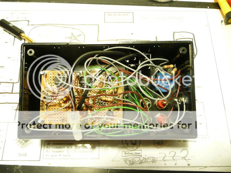
One other hiccup I discovered is that the panel mount fuse holder seems to have been designed for a metal box, so I had to clip some of the plastic tabs off to allow the teeth at either side to come out the top of the box and lock into place. See the pic below for a view of the fuse holder after I removed some of the plastic.

Build hints
The following connections need low resistance - use 22 gauge wire for these.
-U1 pin 4 to 9V power supply (wall wart)
-The mosfet ground (Q3 source) to power supply ground
-Bottom of pot (ground) to pin 4 of U1
-Ground of LM385-2.5 voltage reference to bottom (ground) of pot
This is a picture of the inside of the case to give you an idea of the layout. Though not shown in the schematic or included in the parts list, the wall wart input jack can be seen on the right side. I added it as an afterthought, but I am glad I did. It was snagged from a broken electronic device (old phone). The atrocity that is my soldering is a testament to my lack of proper tools and pertinent experience, but I hope encouraging to those that have never tackled a project like this before. Neither had I...
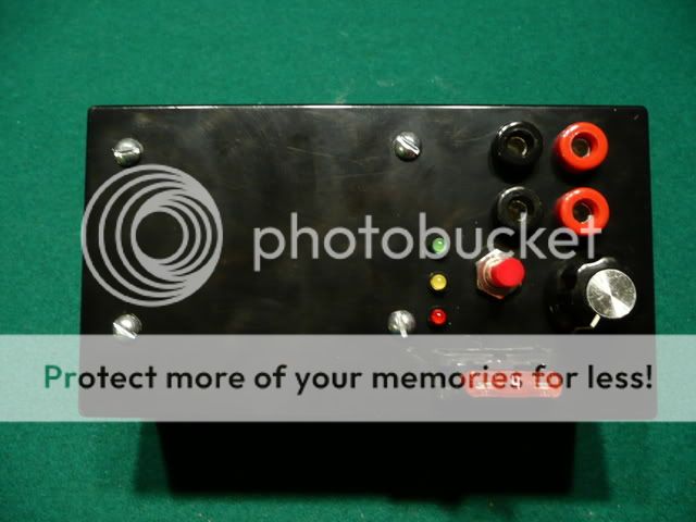
Here is a picture of my finished circuit in its box showing the layout of my controls, inputs and outputs.
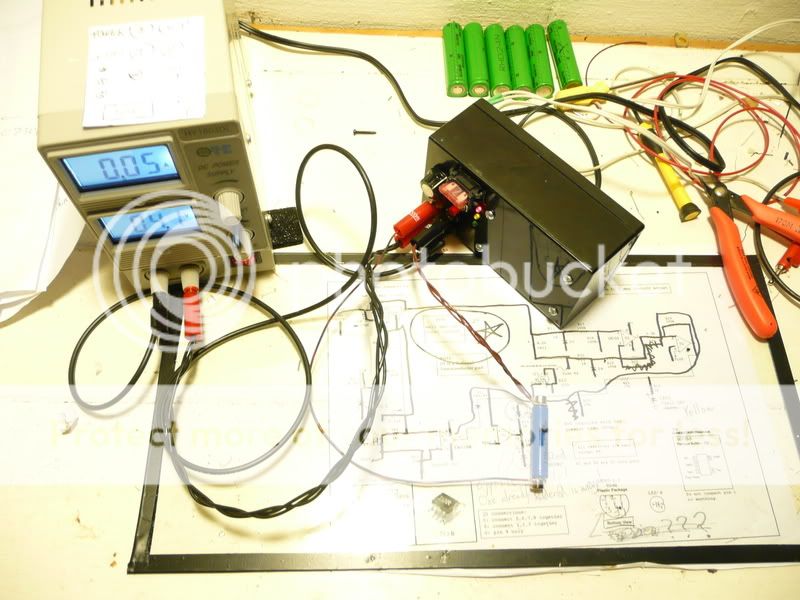
And here is a pic of it charging a 10440 with magnets. A modded cradle to accept all of my cell types has yet to be built, but will really allow me to take advantage of the charger's capabilities. You can also see my power supply (note the extra blue voltage adjustment knob for fine tuning) and you can sort of make out the template laying on the power supply. I made it to mark locations for cutting holes in the case.
Notes
As with other Li-ion chargers, best results are achieved when connections to the cell(s) have low resistance. This can be accomplished by using a cradle or clamp that makes good electrical contact with the cell electrodes.
Thanks
Foremost I would like to thank MrAl for his efforts that made this project possible. He designed and shared something like 20 different versions of a circuit like this with me, and we communicated through hundreds of private messages over about a five month period to hammer out the many design options and troubleshoot the prototype.
I would also like to thank Silverfox for his contributions to the CPF community with respect to knowledge of batteries and the charging thereof, encouraging me to pursue this project and for suggesting that I contact MrAl for help.
Lastly, I would like to thank the members of CPF and all of the staff for providing a haven for enthusiasts such as myself to exchange their ideas and passion about flashlights and related topics.
Last edited: