Poorly modded SSC P7 Mag1D drived by 8xAMC7135 (3x NiMH runtime added)

NetKidz

Enlightened
Joined
Jun 21, 2006
Messages
569
Location
Taiwan
I think it's not too late to join this party. This is my first successfully Mag mod. It's not very good but working. :D

The SSC P7 was from CPFer HgRyu and the bin code is CSX0J. I use two 4x AMC7135 board (DX SKU.1886) wired in parallel. Here's the wire diagram:

MAG-P7-1-driver.gif


I use the cutdown Mag1D from Ledean with stock plastic reflector, UCL lens and DHS heatsink from H22A.


Some pictures in progress:

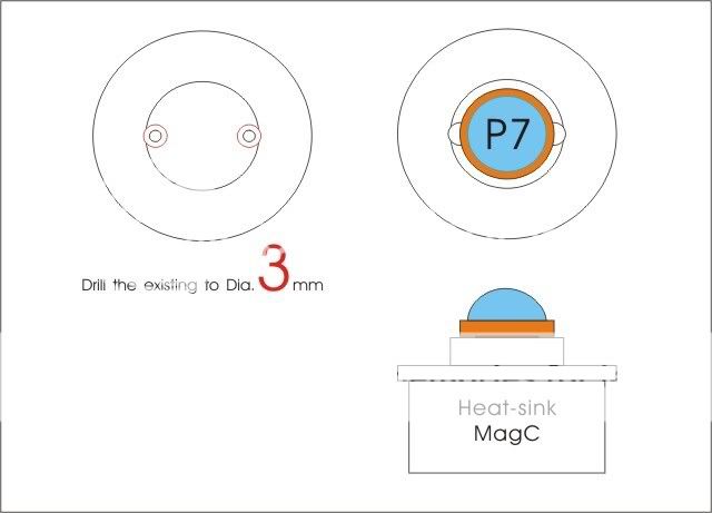
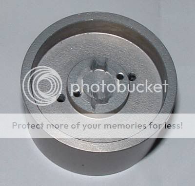
I sand off the centering ridges since the P7 is larger. I only have a small model drill and couldn't drill through the pedestal. Thus, I drill two small holes apart.
MAG-P7-1-01.jpg


I glue two aluminum pieces as heatsink for driver boards using Arctic Alumina Thermal Adhesive. I also put some on the surface to insulate the boards.
MAG-P7-1-02.jpg


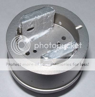
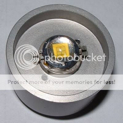
P7 glued on the heatsink using Arctic Silver Thermal Adhesive.
MAG-P7-1-03.jpg


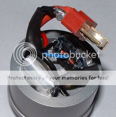
What a mess with wires. :sick2: I know it's overkill using dean connector. I only have it laying around. :green:
MAG-P7-1-05.jpg


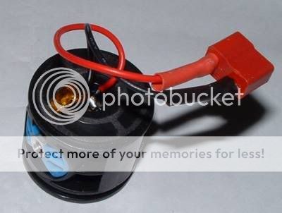
Here's the modded switch.
MAG-P7-1-12.jpg


Put some thermal greases and push the heatsink into Mag body.
MAG-P7-1-13.jpg


Since the wire was apart, I must enlarge the reflector hole a lot. :ohgeez:
MAG-P7-1-14.jpg

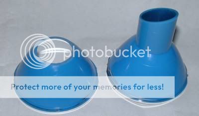
(Left: modded plastic reflector, Right: stock reflector)

Reflector installed.
MAG-P7-1-15.jpg


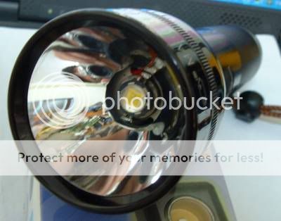
With 4x Eneloop in modamag 4AA holder and KD protected D li-ion.
MAG-P7-1-16.jpg


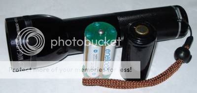
Test the current by DMM, it's about 2.5A for 4x Eneloop in series and about 2.3A for D Li-ion. It may be higher in the Mag with tailcap. (The DMM probe is sharp and the current wasn't stable)

Here's the runtime with 4 eneloop and D li-ion.
MAG-P7-1-RT.gif


It's done by bounce test in my closet. Since the reading is small, the difference is only 1~3 lux, thus change to % will look like big difference. The reading for 4x NiMH and D li-ion is almost the same. I think the driving current is near when in the Mag.

The regulation is flat. The NiMH is cutdown by the driver. The voltage is about 3.8x when take out, but raise to about 4.5x after rest. It's very good that the NiMH won't be over-discharged. :D

The beam isn't perfect but usable. Will try sputtered reflector this weekend if have time. I'm waiting for my second P7 to try the cheap multi-level driver I posted at: https://www.candlepowerforums.com/posts/2402623

Thanks for viewing. ;)


===== 3/31 =====

I put 3x Eneloop and one dummy cell in the 4AA holder to test the runtime again. The initial bounce brightness is near but drops quickly. I think 4x NiMH are needed to stay good regulation. Or maybe AA cell is too small to keep the voltage under that load?

MAG-P7-1-RTb.gif
 
Last edited:

katsyonak

Enlightened
Joined
May 9, 2007
Messages
277
Re: Poorly modded SSC P7 Mag1D drived by 8xAMC7135

That's a very nice mod :thumbsup:
Some glow powder epoxy around the P7 will make it look better IMO, but still I wouldn't call it poorly modded.
 

download

Flashlight Enthusiast
Joined
Jun 26, 2005
Messages
1,630
Location
Sol 3
Re: Poorly modded SSC P7 Mag1D drived by 8xAMC7135

:goodjob: I would suggest to enlarge the original heatsink wiring hole to 3mm or bigger.
Let the hole big enough the emitter can't cover it. No need to enlarge the reflector any more.

P7.jpg
 

NetKidz

Enlightened
Joined
Jun 21, 2006
Messages
569
Location
Taiwan
Re: Poorly modded SSC P7 Mag1D drived by 8xAMC7135

@katsyonak

I didn't handle the heatsink and reflector well. I think it look poorly. :whistle:


@skalomax,

Yes, I'm also surprised by the regulation. I think that's because D li-ion could keep the voltage well enough for the AMC7135. And from SilverFox's test, eneloop could keep about 1.1v under 3A load and 4x eneloop are also good for the regulation. (Vin > Vf + 0.15v)


@download,

That's a good suggestion. I think I should borrow a larger drill next time. :devil:


Thanks all. :)
 

ambientmind

Enlightened
Joined
May 8, 2007
Messages
465
Re: Poorly modded SSC P7 Mag1D drived by 8xAMC7135

Here's the wire diagram:

MAG-P7-1-driver.gif


I'm confused about the wiring on this. So the batt+ and the led+ are the same? these chips just regulate through the (-)? I was thinking of doing the same with these boards, i'll have to try it this way.
 

NetKidz

Enlightened
Joined
Jun 21, 2006
Messages
569
Location
Taiwan
Re: Poorly modded SSC P7 Mag1D drived by 8xAMC7135

Hi ambientmind,

Yes, batt+ and the led+ are wired together. Below is the diagram from datasheet:


AMC7135-diag01.gif


Thanks. :)
 

Isthereanybodyoutthere

Newly Enlightened
Joined
Jan 30, 2008
Messages
170
Re: Poorly modded SSC P7 Mag1D drived by 8xAMC7135

AARGHHH you done it ,,i have to try this mod :huh:

Does anyone have the dimensions for the heat sink
Mostly how thick is the rim that prevents the sink from slip into the mag body
and how deep is the surface that the emitter sits on under the the front part
It looks like the doom of the emitter has to just stick up above the rim
 

NetKidz

Enlightened
Joined
Jun 21, 2006
Messages
569
Location
Taiwan
Re: Poorly modded SSC P7 Mag1D drived by 8xAMC7135 (3x NiMH runime added)

Hi Isthereanybodyoutthere,

Yes, the dome is higher than the rim. I don't have the exact dimension at hand. Maybe you could ask H22A?

Thanks. :)
 

Isthereanybodyoutthere

Newly Enlightened
Joined
Jan 30, 2008
Messages
170
HOW FAR OUT IS THE HEAD SCREWED WHEN YOU HAVE THE SMALLEST FOCUS ??

QUESTION TO THE DRIVERS
dX SELS THEM IN 10 PACKS
BUT I ONLY NEED 2 FOR A MOD LIKE YOURS , BUT I NEED ONE 0,7 AMP DRIVER FOR A INFRARED LED (FROM KAI )
AND 2 OR 3 1 AMPS FOR SOME GOLDEN DRAGONS INFRARED
COULD I JUST DISABLE ONE OF THE MINI DRIVERS ON THE BOARDS TO GET 1 AMP AND 2 TO GET 0,7 AMP
 

Drewfus2101

Enlightened
Joined
Jul 16, 2007
Messages
341
Location
N/A
Wow, 3 nimh's isn't that bad at all. 50 mins to 50%. I wonder how 3 D sized nimh's would do.

The math on that is pretty straight forward. If the batteries are the average 10,000mAh and are 1.2V each, then together you get the 3.6V so although the Vf on the P7 seems to vary slightly, lets say that at 3.6V the current is 2800mA.

10000/2800 = 3.57 hours runtime*

*Assuming everything else is perfect (batteries don't sag in voltage, really hold 10A current, no voltage loss through Mag body, etc....)
 

TorchBoy

Flashlight Enthusiast
Joined
Jan 15, 2007
Messages
4,486
Location
New Zealand
I put 3x Eneloop and one dummy cell in the 4AA holder to test the runtime again. The initial bounce brightness is near but drops quickly. I think 4x NiMH are needed to stay good regulation. Or maybe AA cell is too small to keep the voltage under that load?
Either way, you don't have enough volts. Edit: With three Eneloops.

I wonder how 3 D sized nimh's would do.
SuperFox test, AccuPower D 11500 mAh cells: http://img.photobucket.com/albums/v482/SilverFoxCPF/AccuPowerD11500atVariousRates.gif
SuperFox test, Eneloop AA 2000 mAh cells: http://img.photobucket.com/albums/v482/SilverFoxCPF/EneloopAA2000atVariousRates.gif

At 2 amps they're pretty close, but at 5 amps the D cells are definitely ahead. They would certainly last longer.

Isthereanybodyoutthere, can you please stop shouting?
 
Last edited:

Aircraft800

Flashlight Enthusiast
Joined
Apr 24, 2007
Messages
1,487
Location
DFW Texas.
Is there holes threw the board to make a sandwich? I'm trying to figure out if I can sandwich 4 of these 4x AMC7135 boards together to drive the big PhlatLight 18W LED's. (SST-50)
 

Fulgeo

Enlightened
Joined
Jan 7, 2008
Messages
467
Location
Michigan USA
Is there holes threw the board to make a sandwich? I'm trying to figure out if I can sandwich 4 of these 4x AMC7135 boards together to drive the big PhlatLight 18W LED's. (SST-50)

The old 4xAMC7135 boards sold by DX and KD had holes threw the boards for both the positive and negative supply connections. The newer batches only have decent holes threw the center positive connection and only one diode. The newer 4xAMC7135 boards have small diameter negative holes that either are not big enough for 26 gauge or larger wire or do not go all the way threw the board. I was able to stack 3 of the boards together thou with no problem. I used a 24 gauge wire down the center positive hole, gluing the bottom boards AMC7135 chips to the top boards foil bottom with AA. I used 24 gauge wire to jumper around the edge of each board to connect the negative connections. I used 26 gauge wire for the negative emitter driver wire that comes off each board. Some guyz also just notch the side of the board to run the negatives if they want to stack the driver foil side to foil side. I used this 4.2 amp stacked board I made to drive my first SST-50 build. I used three Accupower Evolution LSD D cells to power this mod. It works great and I did get a measured 4.2 amps out of this rig when the batteries were fully charged. On a side note wanted to say that a 3D Mag with a SST-50 driven at 4.0 - 4.2 amps after being run for 1 hour it about at the edge of heat management. The Flashlight is very warm to the touch as you would hold it but manageable. The head does get uncomfortably hot. I think any more than about 4.2 amps and hour runs would be too hot to hold. The SST-50 at 4.2 is up in the 1000 lumen range. I have metal reflectors that fit my mod but I got the best results using the cut down stock plastic Mag reflector and an aspheric 250 FL lens. Good throw, decent output and relatively few beam artifacts. After an hour of use the stock plastic reflector can hold up to the heat. Also remove or jumper over the diode on each board. This should shave another 0.1 volt off the point were the boards drop regulation and go into DD. Happy Mods.
 
Top