
Sinjz
Flashlight Enthusiast
I've been sitting on a couple of stock Arc LS's for awhile. I'm finally getting around to modding them and would like to up the current. I think they currently run at around 450 ma and I read that if I add a second R15 SMT that it will be boosted up to about 667 ma. Is that right?
Does anybody know where I can find a few R15 SMT resistors? I'm not looking to buy a hundred of them or anything, just want three or four. Thanks.")
Does anybody know where I can find a few R15 SMT resistors? I'm not looking to buy a hundred of them or anything, just want three or four. Thanks.
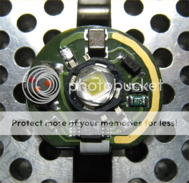


 Not a great soldering job, but it's on there.