For an Android controlled version of this project Andriod Controlled Led Driver
As I was describing my current 42W Torch/Lamp build I realised how simple the basic controller was. So here is the first part of a tutorial on building your own uC Led driver. Enjoy. The tutorial is also on my website at http://www.forward.com.au/uCLedDriver/build_basic_uC_led_driver.html
As this tutorial is too long for a single post I will split it over multiple ones
This first post covers Circuit, Parts, Construction and Software Flow chart.
Note: the heat sink in the photos is gets quite hot running at 500mA. Use a larger one if you want to run continuously at 500mA.
This tutorial describes the construction and programming of a basic pulse width modulator controlled linear current regulator for driving a LED at 500mA. No SMD devices are used. You can use this same basic design for supplying upto 5A or more by changing the current sense resistor.
Construction time 2hrs.
The tutorial covers
The circuit for this basic uC controlled LED driver is
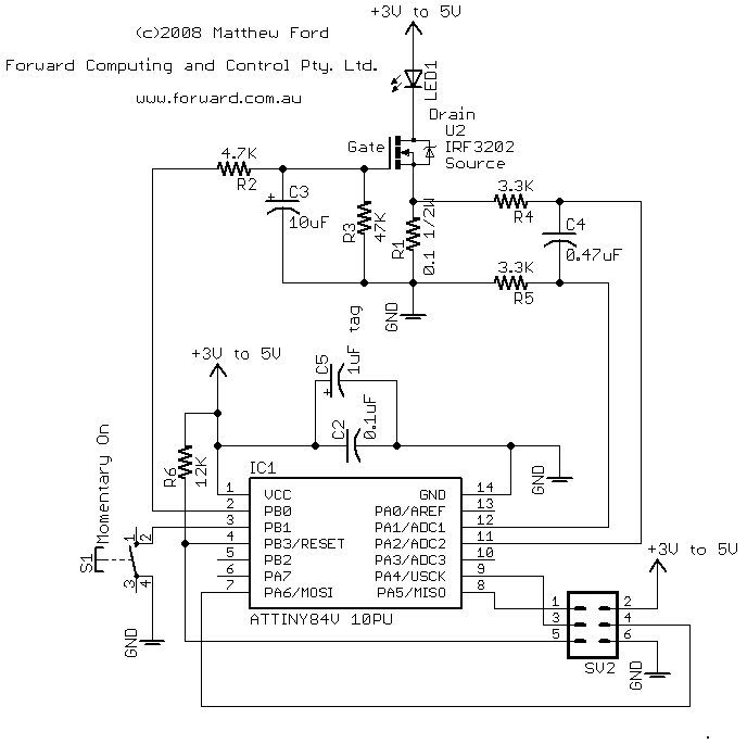
The circuit shown above can be powered from 3 x NiMH batteries or 1 Lithium-Ion battery (or even 3 Alkalines). The uC will work all the way down to 1.8V which is below the fully discharged level of the batteries.
The basic operation of the controller is as follows:-
R1 (0.1ohm) is the current sense resistor. The uC measures the voltage across this resistor to determine the current flowing in the led. If the current is below the required level the uC controller sets the uC output to +5V which charges C3 through R2 raising the gate voltage on the FET U2 this lowers the Fet's resistance and increase the current through the led. IRF3202 is an N-Channel fet which turns on as its gate voltage is increased compared to is source pin. When the current exceeds the required level the uC controller set the uC output to 0V and the discharges C3 so lowering the voltage on the Fet's gate and so increasing the Fet's resistance and reducing the current though the Led.
R3 is there to make sure the Fet gate has zero Volts (i.e. Fet is OFF) when the control uC circuit is powered down.
R2 and R3 form a voltage divider from the uC output to ground which limits the maximum voltage that can be applied to the gate of the Fet. With the values shown the maximum fet gate voltage is about 4.55V.
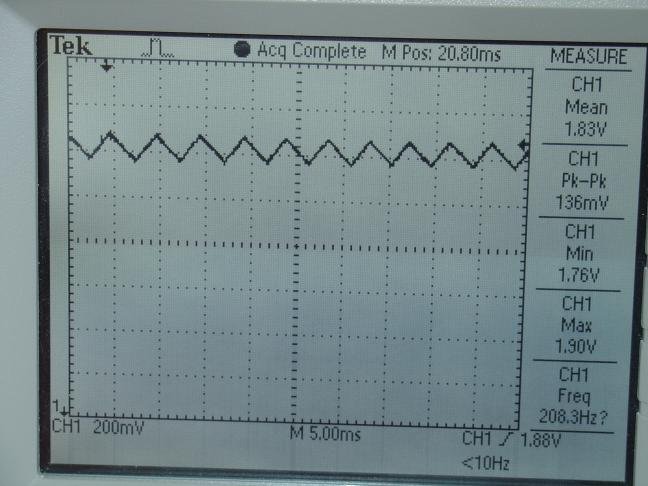
This is called BangBang control and is simple and effective. The capacitor, C3 smooths out the square wave output from the uC so the Fet gate sees only a small ripple.
R4, R5 and C4 form an RC filter for the current sense voltage applied to the uC differential Analog to Digital 10 bit converter. The uC has an internal gain of x20 applied to this signal and then converts the differential voltage to a count between 0 and 1023, where 1023 equals 1.1V (approximately). Dividing 1.1V by the internal gain of 20 implies that full range on the input to the uC is about 55mV. With a sense resistor of 0.1ohm this means full range current is 55/0.1 = 550mA. Of course you can change the full range current by changing the sense resistor.
C2 and C5 are supply filtering for the uC and R6 is the Reset pull-up resistor.
Parts
The parts list is:-
Part Value
C2 0.1uF ceramic
C3 10uF tag
C4 0.47uF
C5 1uF tag
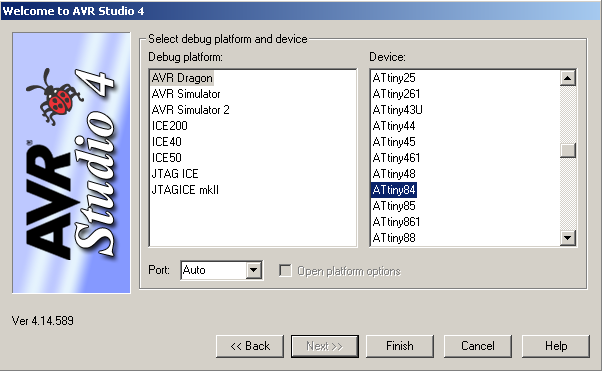
IC1 ATTINY84V 10PU
LED1 K2 LUMILED + heatsink
R1 0.1 1/2W
R2 4.7K
R3 47K
R4 3.3K
R5 3.3K
R6 12K
S1 Momentary On
SV2 6PIN HEADER
U2 IRF3202
Veroboard with copper tracks on the back
500mA power pack 3 to 12V selectable
For programming the uC you will need
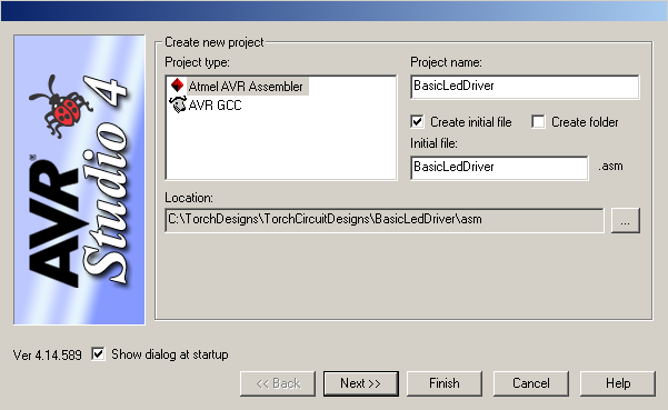
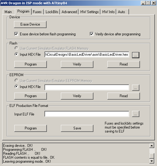
AVRStudio4 (free download)
AVR Dragon programming board (~$50)
6pin header cable
USB cable + Window 2000/XP/Visa computer
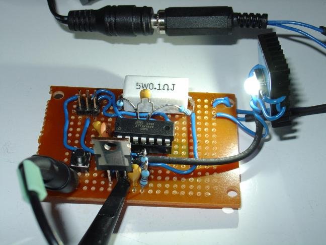
As you can see from the photo my sense resistor (0.1 ohm) is a 5W resistor. Only a 1/2W resistor is needed but this was what I had to hand. The uC is an Atmel Attiny84V 10PU. Note the V suffix this indicates the low voltage part which will run down to 1.8V. The Led heat sink I used was CPU self adhesive heat sink. If you use a normal heat sink you will also need some thermal epoxy to attach the led to the heatsink.
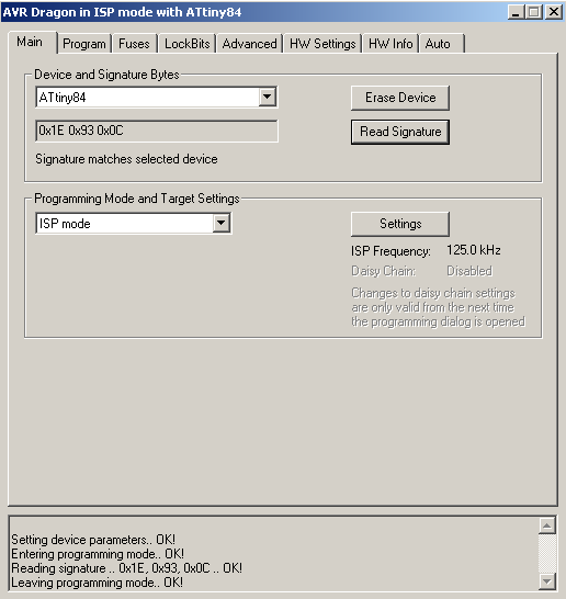
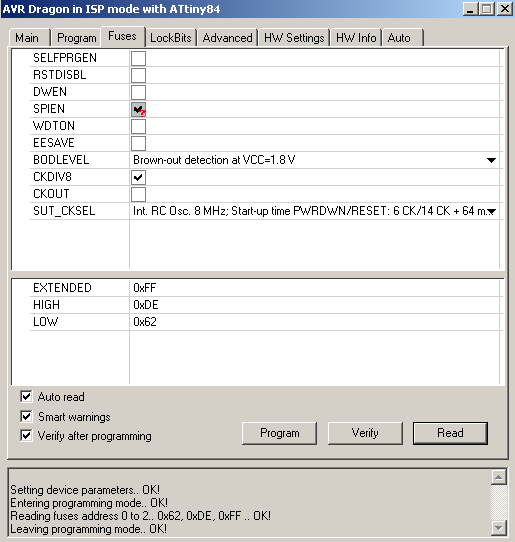
The AVR Studio 4 provides the code compiler and runs the AVR Dragon programmer. You can download AVR Studio 4 from www.atmel.com (as at July 2008 the direct link is http://www.atmel.com/dyn/Products/tools_card.asp?tool_id=2725 scroll down to the Software section and choose AVR Studio 4.14). AVR Dragon is available from Digiky (and others) in the US and Avnet in Australia. There are other software compilers available that run under Linux (google avr programmer linux).
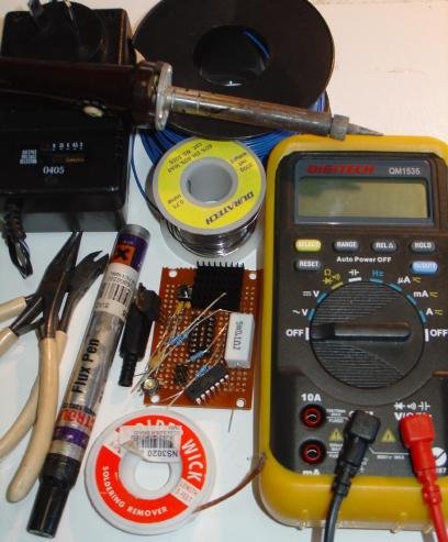
Other items you need are a fine tipped soldering iron (20W is OK), some solder and a multimeter and tools. I also suggest solder wick and a flux pen.
The power pack's output voltage is selectable from 3V to 12V.
Do not select an output voltage above 4.5V as the normal maximum running voltage for the uC is 5V.
Construction
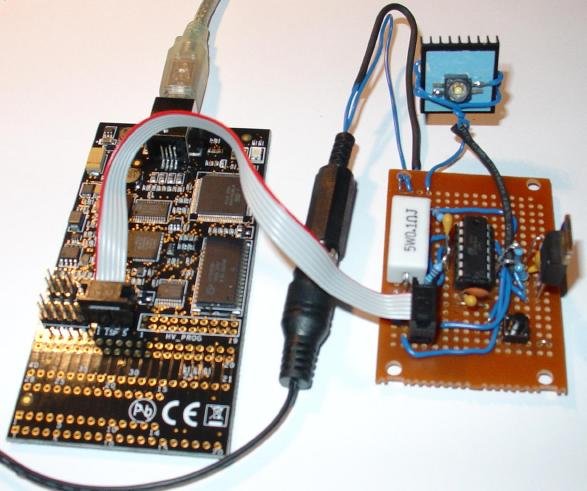
After 2hrs work I had this
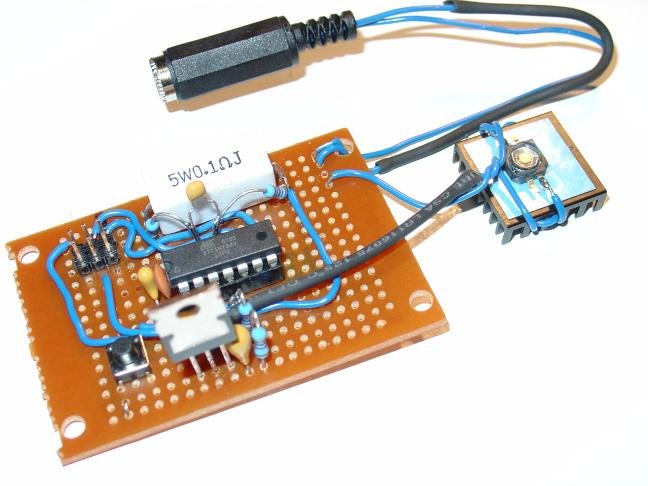
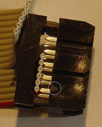
The only messy part is the 6 pin header which did not fit neatly into the layout of the copper tracks on the back of the veroboard. I had to cut away some track connections to wire the header up.
Before inserting the uC, plug in the power pack and check the voltage at pin 1 and 14 of the uC. Pin 1 should be +Volts. Also check Pin 4 for +Volts and pin 2 of the 6 pin programming header. Double check the connections and orientation of the 6 pin programming header.
Software Design (Flow chart and outline of code)
The uC's I use are from the Attiny series by Atmel. This design uses the Attiny84V which has 8K of programmable memory, 512 bytes of EEPROM and
512 byte of RAM.
I use a very basic program flow, shown below
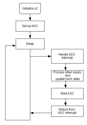
This uses only one interrupt, the ADC conversion complete interrupt. It has the advantage of simplicity and low noise since there is no processing or output pin changes while the ADC conversion is running. It has the disadvantage of reducing the sampling rate of the ADC since all the input and output processing is done each ADC cycle. However my present code still has a sampling rate of about 5300 samples/sec which is more than enough for controlling a torch.
The Attiny84 has a number of built in timers. I don't use any of these. Instead I run my own counters from the ADC loop to generate timers of 1/100 sec and 1/10sec and 1/2sec. Because the ADC loop times vary depending on the processing being done these timers are only approximate but appear to be with in +/- 5%.
An outline of the code is shown below
//---- MAIN PROGRAM --------------------------------------------
.org 0x0000
rjmp RESET
......
.org ADCCaddr// = 0x000b ; ADC Conversion Complete
rjmp ADC_INT
....
RESET:
// initialize uC here
...
sei // enable interrupts
E_LOOP:
// set up for ADC conversion and then sleep
ldi Temp, (1<<SM0) | (1<<SE)
out MCUCR, Temp // ADC noise reduction rest zero, enable sleep
sleep // goto sleep this starts the ADC
// wake up on ADC interrupt
// on completion of interrupt returns here
rjmp E_LOOP // loop for next ADC
//----END MAIN PROGRAM --------------------------------------------
//----HANDLE ADC INTERRUPT ----------------------------------------------
ADC_INT:
// save ADC results
in ADCLow,ADCL
in ADCHigh,ADCH
.....
// process the ADC measurement of current, voltage, etc
.....
// all paths jmp to here
END_ADC_INT:
rcall SWITCH_DEBOUNCE // every ADC cycle about 5kHz
rcall INCREMENT_100HZ_TIMER // may set volts or temp flag
rcall PROCESS_STATE_TRIGGERS
reti // return from interrupt, interrupts enabled here
//----END ADC_INT -------------------------------------------------
See later post for full code of the basic led driver
As I was describing my current 42W Torch/Lamp build I realised how simple the basic controller was. So here is the first part of a tutorial on building your own uC Led driver. Enjoy. The tutorial is also on my website at http://www.forward.com.au/uCLedDriver/build_basic_uC_led_driver.html
As this tutorial is too long for a single post I will split it over multiple ones
This first post covers Circuit, Parts, Construction and Software Flow chart.
Note: the heat sink in the photos is gets quite hot running at 500mA. Use a larger one if you want to run continuously at 500mA.
This tutorial describes the construction and programming of a basic pulse width modulator controlled linear current regulator for driving a LED at 500mA. No SMD devices are used. You can use this same basic design for supplying upto 5A or more by changing the current sense resistor.
Construction time 2hrs.
The tutorial covers
- Circuit
- Parts
- Construction
- Software Design (Flow chart and outline of code)
- Complete Code (in later posts)
- Programming the uC (in later posts)
- Debugging the code in circuit (in later post)
- Extensions (in later posts)
The circuit for this basic uC controlled LED driver is
The circuit shown above can be powered from 3 x NiMH batteries or 1 Lithium-Ion battery (or even 3 Alkalines). The uC will work all the way down to 1.8V which is below the fully discharged level of the batteries.
The basic operation of the controller is as follows:-
R1 (0.1ohm) is the current sense resistor. The uC measures the voltage across this resistor to determine the current flowing in the led. If the current is below the required level the uC controller sets the uC output to +5V which charges C3 through R2 raising the gate voltage on the FET U2 this lowers the Fet's resistance and increase the current through the led. IRF3202 is an N-Channel fet which turns on as its gate voltage is increased compared to is source pin. When the current exceeds the required level the uC controller set the uC output to 0V and the discharges C3 so lowering the voltage on the Fet's gate and so increasing the Fet's resistance and reducing the current though the Led.
R3 is there to make sure the Fet gate has zero Volts (i.e. Fet is OFF) when the control uC circuit is powered down.
R2 and R3 form a voltage divider from the uC output to ground which limits the maximum voltage that can be applied to the gate of the Fet. With the values shown the maximum fet gate voltage is about 4.55V.
This is called BangBang control and is simple and effective. The capacitor, C3 smooths out the square wave output from the uC so the Fet gate sees only a small ripple.
R4, R5 and C4 form an RC filter for the current sense voltage applied to the uC differential Analog to Digital 10 bit converter. The uC has an internal gain of x20 applied to this signal and then converts the differential voltage to a count between 0 and 1023, where 1023 equals 1.1V (approximately). Dividing 1.1V by the internal gain of 20 implies that full range on the input to the uC is about 55mV. With a sense resistor of 0.1ohm this means full range current is 55/0.1 = 550mA. Of course you can change the full range current by changing the sense resistor.
C2 and C5 are supply filtering for the uC and R6 is the Reset pull-up resistor.
Parts
The parts list is:-
Part Value
C2 0.1uF ceramic
C3 10uF tag
C4 0.47uF
C5 1uF tag
IC1 ATTINY84V 10PU
LED1 K2 LUMILED + heatsink
R1 0.1 1/2W
R2 4.7K
R3 47K
R4 3.3K
R5 3.3K
R6 12K
S1 Momentary On
SV2 6PIN HEADER
U2 IRF3202
Veroboard with copper tracks on the back
500mA power pack 3 to 12V selectable
For programming the uC you will need
AVRStudio4 (free download)
AVR Dragon programming board (~$50)
6pin header cable
USB cable + Window 2000/XP/Visa computer
As you can see from the photo my sense resistor (0.1 ohm) is a 5W resistor. Only a 1/2W resistor is needed but this was what I had to hand. The uC is an Atmel Attiny84V 10PU. Note the V suffix this indicates the low voltage part which will run down to 1.8V. The Led heat sink I used was CPU self adhesive heat sink. If you use a normal heat sink you will also need some thermal epoxy to attach the led to the heatsink.
The AVR Studio 4 provides the code compiler and runs the AVR Dragon programmer. You can download AVR Studio 4 from www.atmel.com (as at July 2008 the direct link is http://www.atmel.com/dyn/Products/tools_card.asp?tool_id=2725 scroll down to the Software section and choose AVR Studio 4.14). AVR Dragon is available from Digiky (and others) in the US and Avnet in Australia. There are other software compilers available that run under Linux (google avr programmer linux).
Other items you need are a fine tipped soldering iron (20W is OK), some solder and a multimeter and tools. I also suggest solder wick and a flux pen.
The power pack's output voltage is selectable from 3V to 12V.
Do not select an output voltage above 4.5V as the normal maximum running voltage for the uC is 5V.
Construction
After 2hrs work I had this
The only messy part is the 6 pin header which did not fit neatly into the layout of the copper tracks on the back of the veroboard. I had to cut away some track connections to wire the header up.
Before inserting the uC, plug in the power pack and check the voltage at pin 1 and 14 of the uC. Pin 1 should be +Volts. Also check Pin 4 for +Volts and pin 2 of the 6 pin programming header. Double check the connections and orientation of the 6 pin programming header.
Software Design (Flow chart and outline of code)
The uC's I use are from the Attiny series by Atmel. This design uses the Attiny84V which has 8K of programmable memory, 512 bytes of EEPROM and
512 byte of RAM.
I use a very basic program flow, shown below
This uses only one interrupt, the ADC conversion complete interrupt. It has the advantage of simplicity and low noise since there is no processing or output pin changes while the ADC conversion is running. It has the disadvantage of reducing the sampling rate of the ADC since all the input and output processing is done each ADC cycle. However my present code still has a sampling rate of about 5300 samples/sec which is more than enough for controlling a torch.
The Attiny84 has a number of built in timers. I don't use any of these. Instead I run my own counters from the ADC loop to generate timers of 1/100 sec and 1/10sec and 1/2sec. Because the ADC loop times vary depending on the processing being done these timers are only approximate but appear to be with in +/- 5%.
An outline of the code is shown below
//---- MAIN PROGRAM --------------------------------------------
.org 0x0000
rjmp RESET
......
.org ADCCaddr// = 0x000b ; ADC Conversion Complete
rjmp ADC_INT
....
RESET:
// initialize uC here
...
sei // enable interrupts
E_LOOP:
// set up for ADC conversion and then sleep
ldi Temp, (1<<SM0) | (1<<SE)
out MCUCR, Temp // ADC noise reduction rest zero, enable sleep
sleep // goto sleep this starts the ADC
// wake up on ADC interrupt
// on completion of interrupt returns here
rjmp E_LOOP // loop for next ADC
//----END MAIN PROGRAM --------------------------------------------
//----HANDLE ADC INTERRUPT ----------------------------------------------
ADC_INT:
// save ADC results
in ADCLow,ADCL
in ADCHigh,ADCH
.....
// process the ADC measurement of current, voltage, etc
.....
// all paths jmp to here
END_ADC_INT:
rcall SWITCH_DEBOUNCE // every ADC cycle about 5kHz
rcall INCREMENT_100HZ_TIMER // may set volts or temp flag
rcall PROCESS_STATE_TRIGGERS
reti // return from interrupt, interrupts enabled here
//----END ADC_INT -------------------------------------------------
See later post for full code of the basic led driver
Last edited:
")