
I put this together a couple of weekends ago but due to a combination of being busy, limited 'net access and not being particularly original, have only just got round to posting. Actually, I wasn't going to bother but there has been a question about KD D Lion cells and my driver solution is a bit outside the usual AMC 7135.
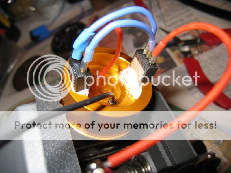
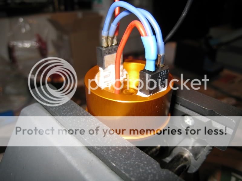
LM338T & resistor (both in T0220 cases) mounted to H/S with Arctic Alumina epoxy, wire is 22AWG (I think) silicone.
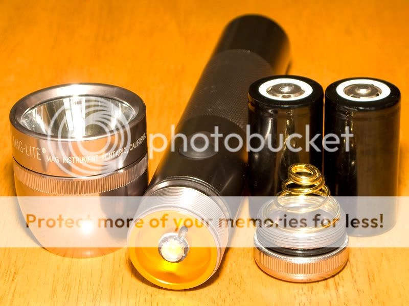
KD spring needs tip bending in and down to stop it drilling through the bottom of the cells


Two KD Li-ion cells fit reasonably with the short spring — My driver solution wastes a bit more voltage than the AMC7135 boards so one cell won't do.


Beamshots — These are a fortnight old and I've forgotten which ones are which. I'll do some more carefully if the weather is good enough this weekend.


Kev.
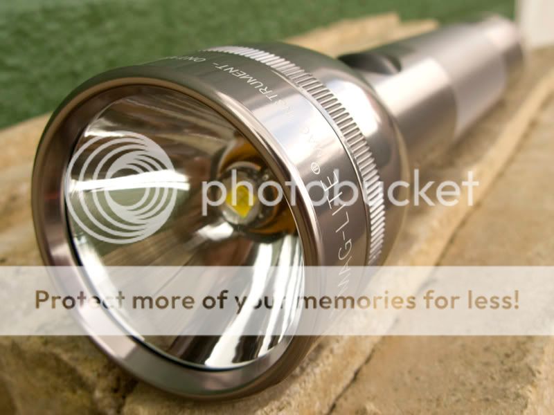
- Silver/Pewter 2D Mag
- Litemania H/S
- KD reflector (SMO or MOP, currently undecided on a permanent choice, leaning towards smooth)
- Option of KD Aspherical Lens (Jury also still out)
- LM338T Variable voltage regulator configured for 2.5A constant current
- Two KD D Lion Cells
LM338T & resistor (both in T0220 cases) mounted to H/S with Arctic Alumina epoxy, wire is 22AWG (I think) silicone.
KD spring needs tip bending in and down to stop it drilling through the bottom of the cells
Two KD Li-ion cells fit reasonably with the short spring — My driver solution wastes a bit more voltage than the AMC7135 boards so one cell won't do.
Beamshots — These are a fortnight old and I've forgotten which ones are which. I'll do some more carefully if the weather is good enough this weekend.
Kev.

 .
.


")