DIY Li-Ion protection.

VanIsleDSM

Enlightened
Joined
Oct 16, 2007
Messages
649
Location
Victoria BC, Canada.
I'm building a light with 6x 10440 cells in seires, they will be taken out of the light to charge individually, so that's no issue, but I'd like to make sure none of them are over discharged in the light.

I'm somewhat electrically savvy, so I looked into the different chips available to make my own, though nothing I easily found through my normal avenues looked to be a good candidate.

Then I was directed here:

http://www.batteryspace.com/index.asp?PageAction=VIEWCATS&Category=711

This looks like a great bet, Although the low V cutoff is a little lower than I'd like, they'll still work just fine. I tried to order a few of the very top protection board, came to $9, then they wanted $50 for shipping to Canada through UPS express. Hopefully there is another option, I've emailed them to find out.

In the meantime, how many other people make their own battery packs with protection? Where do you get protection circuits? There must be somewhere else.. if this place can't come down on the shipping, it would cost me less to order 14500 cells from DX and strip the protection PCB from them.

I've heard much about Mr. AW and his batteries. I imagine he orders standard cells in bulk and fits them with protection circuits for resale? I wonder if the protection circuits are available on their own. I'm sure that's probably been discussed already, so before I bother him to ask a question that me be asked all the time, I thought I'd just mention that here and hopefully get a response from someone else who knows.
 
Last edited:

mdocod

Flashaholic
Joined
Nov 9, 2005
Messages
7,544
Location
COLORado spRINGs
I have to ask, what on earth are you going to drive with 6 10440s in series?? Considering the realistic capacity of a 10440 cell, you'll end up with a nice chunk of voltage, but very little potential current. there are usually much better power storage solutions than AAA size cells in pretty much any chemistry when you start dealing with 3 or more cells. (in which case, single larger cells with far more watt-hours of stored energy will fit in the same place).

hehe
Eric
 

Illum

Flashaholic
Joined
Apr 29, 2006
Messages
13,053
Location
Central Florida, USA
honestly I don't know what VanIsleDSM may be up to....but for the low capacity high voltage yield from 6x10440s sounds like hes building a cow prod:candle:
 

VanIsleDSM

Enlightened
Joined
Oct 16, 2007
Messages
649
Location
Victoria BC, Canada.
I don't want to send the thread too off topic, but sometimes a higher voltage is more desirable. Buck drivers are inherently more efficient than boost drivers. And if I were to use less quantity of larger cells the current draw from the cells would be much greater, and we all know Li-Ion last longer when sipped upon. Beyond that, high voltage is inherently more efficient as well.

I weighed all the options for what I want to build, and 6x 10440 happens to work better than anything else for this project with the space I have.
 
Last edited:

mdocod

Flashaholic
Joined
Nov 9, 2005
Messages
7,544
Location
COLORado spRINGs
Sorry I'm going to keep it off track to make a point here:

The true capacity of a 10440 size li-ion is about 300mAH from what I understand. (some higher some lower, depends on load).

The total watt-hours of a 6x10440 pack will be about 6.66 watt-hours. maximum safe current draw is about 500-600mA. or about 12 watts for about 30 minutes.

A single 18650 size li-ion cell has about 7.4 watt-hours of stored energy, can be easily protected with a single PCB and no special complicated charging requirements above and beyond single cell charging. The maximum safe discharge for an 18650 is about 4 amps, or almost 15 watts for about 30 minutes.

yes buck is more efficient than boost. Often buck is 95%, while boost is 80%, but the 18650 has at least 12% better capacity than 6x 10440s, taking a 3% hit on runtime IMO is well worth the fact that the 1x18650 is a smaller and far less complicated setup than 6x 10440.

Eric
 

VanIsleDSM

Enlightened
Joined
Oct 16, 2007
Messages
649
Location
Victoria BC, Canada.
Yes.. it would be better if my design didn't require a higher voltage. Try boosting one cell to ~15V and see the slightly larger capacity will pay off.
 

mdocod

Flashaholic
Joined
Nov 9, 2005
Messages
7,544
Location
COLORado spRINGs
I'm assuming 4-5 LEDs in series if you are looking at 15V requirements.

Assuming the 22.2V pack, with a maximum output at say, 550mA from the pack, means at ~15V at the LEDs you are looking at driving them probably at a 700mA (pretty common drive level setting on a regulator). 1A would be too high but 700mA would keep the cells safe.

so the trick then, is to find a power solution and boost converter that outperforms that option, is simpler by means of requiring less cells to deal with, is available with PCB built in etc etc.

A pair of 18500 cells would have less overall diameter, and only be 12mm longer than 6AAAs in a 3 abreast configuration. You'd have ~7.4V to work with, A maxflex 2 drawing ~1.5A would drive 4 LEDs in series at around 720mA with ~88% efficiency. Well below the maximum capabilities of the driver, which, when properly heat-sinked, can operate at input currents of up to 3A. You could actually push 1A across 4 LEDs with this driver from 2 li-ion cells, be drawing around 2.25A from the cells, which is fine, because the 18500s have ~1400-1500mAH capacity, 2.5A (or even a little higher) is considered safe and reasonable. In most operating configurations the maxflex is better than 85% efficient.

2 18500 cells: ~10watt-hours.
6 10440 cells: ~6.6watt-hours.

I understand you probably have your heart set on a particular design, I'm just trying to but in here and try to point out that there are a number of alternative solutions that most people would consider to be better.

Trying to put together enough voltage in a small place to use the convenience of buck regulation means using lots of smaller cells with lower energy density than their larger cousins. In many cases, it's worth trading off some efficiency and just putting more actual power into the equation from the get go.
 

VanIsleDSM

Enlightened
Joined
Oct 16, 2007
Messages
649
Location
Victoria BC, Canada.
You're being fairly bias in your direction with your calculations.

You take into account the over rating of 10440s, but not the over rating of 18500s, especially at high current draw. I've also heard 10440s are more like 320mAh, and 18500s would not only be about 12mm longer, would be more like 30mm longer with the protection PCBs. That's far too big for what I need.

My driver is around 94% efficient, while you would have slightly more runtime on 2 18500s, the light would be 3cm longer and a good bit less efficient overall.

If you'd like to discuss battery options and divers further we should do it somewhere else. I'd like to get this thread back on topic.

I heard back from batteryspace.com. I didn't get a completely clear answer yet, but it appears they will only ship UPS or Fedex express, which is $50.. so forget that. They were of some help though, as I sourced the chip used in their designs, and it will work perfectly for me, though it looks like it'll cost me more than they are charging to build them myself.. no matter, I refuse to pay such ridiculous shipping when the shop owner could easily send these PCBs in a ~$5 padded envelope with USPS.
 

mdocod

Flashaholic
Joined
Nov 9, 2005
Messages
7,544
Location
COLORado spRINGs
the protection circuit on an 18500 is available contained with the 50mm length and does not require anything else to be added. 12mm is how much longer 2 PROTECTED 18500s will be compared to a set of bare 10440s in 3 abreast configuration, you have to add protection to the 10440. You have stated you believe that the protection circuits will add, 18mm in length (30-12), so then I guess the 10440 pack would actually end up 6mm longer than the 18500 pack.

As tested by Silverfox:
protected 18500, microfire brand: 1.3AH true capacity into a 2-3 amp load.
protected 18500, pila brand: 1.25AH true capacity into a 2-3 amp load.
protected 18500, wolf-eyes brnad: 1.2Ah true capacity int a 2-3 amp load.

these are tests of cells from quite a few years ago, as I understand it, pretty much every brand of cell sold as a protected cell for flashlight use has gone through at least 1 or more revisions since that time. I would not be surprised at all to see AWs 18500 cell perform very close to 1.4AH into a 2A load. But I have not seen a discharge graph for it so can't say for sure.

Assuming the worst case scenario, you draw 3 amps from a pair of 18500 cells made 3 years ago, that's still 9 watt-hours or better. 35% better capacity than 6 10440s, and fits in less space than the 10440s after you add protection to the 10440s. So you end up with a smaller pack with more capacity, you could setup a boost driver ~60% efficient and still have the same runtime as the 10440 design.

I know you want me to let this go, I know you have made up your mind, I just can't fathom why go through all the hassle of building your own PCBs for a complicated 6 cell pack when you can reduce costs, get shipping on protected cells direct to canada for a couple bucks direct from AW in his sales thread.

Yes, I'm prodding and poking all the places you don't want me going near. You've decided you are going a route and want information on how to make that route work. I'm showing you a different route that is far easier and cheaper. You don't have to go down my road, but I'm telling ya, the road ahead of you on your current heading is looking like you might want to bring a tow strap.
 

Tohuwabohu

Newly Enlightened
Joined
May 8, 2008
Messages
184
Location
Germany
Do you really need a separate protection circuit for each of the cells?
You could use an IC like the MAX1665 to protect up to 4 cells.
For 6* 10440 you would only need 2 MAX1665 and 4 N-channel MOSFETs.
 

SilverFox

Flashaholic
Joined
Jan 19, 2003
Messages
12,449
Location
Bellingham WA
Hello VanIsleDSM,

Since you are designing the whole circuit, and plan to charge the cells separately outside the device, I think all you need is a global low voltage cut off.

If you anticipate a high current draw, you can set the low voltage cut off at 2.5 volts per cell. If you have a moderate or low current draw, you can adjust that up to 2.8 - 3.0 volts per cell. The key is that at the end of the discharge, the rebounded voltage should be around 3.3 volts per cell, or higher.

Quality cells will have internal short protection built into the cell, the over voltage concern will be handled by the charger used to charge the cells, and the maximum current draw is limited by design.

Tom
 

VanIsleDSM

Enlightened
Joined
Oct 16, 2007
Messages
649
Location
Victoria BC, Canada.
mdocod,

You really think you know better, yet you still don't even know exactly what I'm doing. I find that pretty funny. You're option is not better, it does not work for what I want to do, and you are wrong about the protection being included in the 50mm length. I have some 18650s here that measure close to 18900, and i always hear people talking about protected circuits being longer.. well of course they are.. they have PCBs on the end. It will not be 12mm longer, it will be about 30mm longer, and this will not work.

You also make assumptions, that my own protection will increase the length. Do you know how I plan to build things exactly? The protection won't go on the ends to increase the length.

You claim to be showing me an easier road, that's quite a claim. I don't want to sound rude, but you've shown me absolutely nothing. I'm not the kind of person who doesn't weigh his options before building something. So you need not worry, I'm afraid your 18500 love affair has no place with my project :)

Then your toe strap comment.. well.. that's just an insult to what you think my capabilities are.. of which I have received many, and I love imagining the look on the faces of people who say such things after I present my finished projects.
 

VanIsleDSM

Enlightened
Joined
Oct 16, 2007
Messages
649
Location
Victoria BC, Canada.
SilverFox,

Thanks for your reply. I think I've actually got it pretty figured quite economically. I'm just getting some other stuff together and I'll make the order. I'll be using virtually the same chips as all protection PCBs I've seen. Pretty simple, couple external resistors, 1 cap, and 2 P channel MOSFETs, cost me about $2/battery. So each battery will have it's own protection.. The way I end up rigging the protection to them.. they might just end up being charged with it in place too.

The cutoff voltages are preprogrammed into this chip, an advantage that there are less external programming components, but a disadvantage that you can't change things yourself unless you order a different chip, which may not be in stock. The one I'm getting is 4.325V-2.5V. Near the end of the charge the battery will be putting out 400-600mA depending on what the output is set to, so I think the 2.5V cutoff will work well.
 
Last edited:

VegasF6

Flashlight Enthusiast
Joined
Dec 5, 2007
Messages
1,449
Location
Las Vegas
VanIsle, I don't know if it still fits in your plan, but perhaps you can ask another member to broker the deal for you with battery space. For instance, I am in Nevada, 3 of the top board on that site cost 7.02 to ship to me. I imagine you could simply pay and have them drop shipped to me or better still a member closer in the US and then have them shipped to you from there? Still not the cheapest option I know, but beats out 50$!
 

mdocod

Flashaholic
Joined
Nov 9, 2005
Messages
7,544
Location
COLORado spRINGs
Hello VanIsleDSM

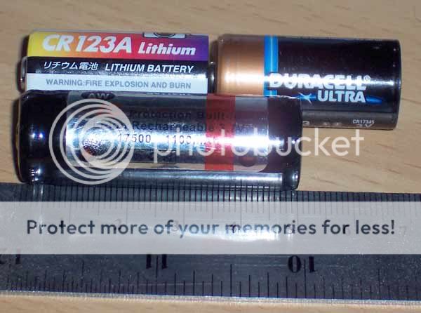
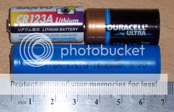
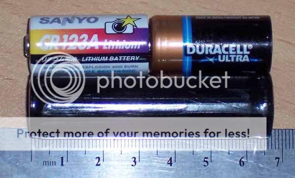
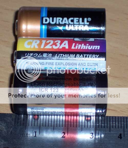
and you are wrong about the protection being included in the 50mm length.

A picture of a protected 3.7V AW brand 17500 cell, a measuring stick and a pair of convincers (well known to be ~34mm long, so you don't think I'm trying to mislead you with a trick ruler or anything):
100_3140.jpg


A picture of a protected 3.7V AW brand 17670 cell (from a few years ago, blue label):
100_3136.jpg


A picture of a protected 3.7V AW brand 18650 cell:
100_3135.jpg


A picture of a 3.7V AW brand protected RCR123 (16340).
100_3141.jpg


----------------------------------------------------------

You also make assumptions, that my own protection will increase the length. Do you know how I plan to build things exactly? The protection won't go on the ends to increase the length.

I'm not the only one making assumptions. I made an assumption based on figures you provided, nothing wrong that doing that, it happened to be a wrong assumption, just like your assumption that a protected cell has to be longer than an unprotected cell. They make the cell within slightly shorter, and have modern PCBs that are only a few mm thick. Works great.

----------------------------------------------------------

The tow strap comment was not intended as an insult, it was intended as a funny analogy with no deeper meaning. I apologize If I have caused any hard feelings.

----------------------------------------------------------

Eric
 

VanIsleDSM

Enlightened
Joined
Oct 16, 2007
Messages
649
Location
Victoria BC, Canada.
It looks like AW's cells stay closer to a stock form, but you're still not measuring the button. A pair of calipers would be much better. My trustfire cells are 68.2mm long, not 65mm. How thin you make the PCB isn't the big deal, thin PCB boards aren't new technology, you still have to solder chips onto it that are Xmm thick.

I wanted to get into this at the appropriate time when I'm ready to make that thread, but you're really trying to drag me in. I haven't read everything about the maxflex, but it appears the output current is preset in the software? That wouldn't work for me. This solution is also ultimately longer, and far less efficient, especially as the cells start dropping voltage. The driver I designed will also be able to put out 1amp until the 10440s reach ~3.2V, then the LED current will start to drop in order not to pull too much current from the 10440s, though I only plan to run 900mA max for this project. This dimming will also a good indication of a dieing battery before the protection kicks in. I'm not so sure maxflex could do 1amp through 4 LEDs from 2 cells.. and I know the efficiency would definitely suffer.. it already drops off quite a bit as the cells fall in voltage. It would require a heatsink. Adding extra watts of heat to a small light is not what I want to do, drop the light output and efficiency even more. The LEDs will dissipate enough heat, keeping all other heat dissipation low is a priority. You're looking at things in too simple of a manner, somewhat akin to American auto makers, larger cells with more power isn't always better, You can do the same thing on less power will better results and more efficiency overall.. but yes, it is slightly more complicated.. just like adding a turbo to a 2.0L.

p.s. I never provided "figures" that I was putting the cell protection on top of the cells :)

No offense has been taken, I just think you should be a little more modest with your opinions. You don't know exactly what I'm doing or what my goals are, and you haven't taken everything into account, I have.
 
Last edited:

kurni

Enlightened
Joined
Aug 7, 2006
Messages
529
Location
Sydney, Australia
:cool: take a chill pill everyone :crazy:

All VanIsleDSM wants is a DIY LiIon protection.

Whether he want to use 10440 or 10180 it's his business; I am curious as well but I'm mindful about the direction of the thread.

VanIsleDSM, I have to say 6x 10440 in series is somewhat unique, I am looking forward to seeing your complete build :thumbsup:

Cheers,
Kurni
 

mdocod

Flashaholic
Joined
Nov 9, 2005
Messages
7,544
Location
COLORado spRINGs
Howdy VanIsleDSM,

I can't in good conscience leave it alone if I know that I can make suggestions for an improved design. I don't mean to be a rock in your shoe on this - but I can't in good conscience not at least observe the design and point out possible safety issues or possible ways to simplify the design that can improve safety or performance.

I know it's not necessarily any of my business to prod into everyones doings with a li-ion cell, but if I can prevent just 1 disaster it would all be worth it. I've already stepped in and diagnosed or identified a number of problems over the years with CPFers configurations that had they gone unchecked, could have led to something disastrous happening. Yea, I probably come across like the li-ion police or something. Oh well. In the end, it's not a bad thing.

Before (in post 13 above) you expressed that you like to weigh your options before building. I don't doubt that you have weighed many options, I simply offer the possibility that some of those options may have been weighed with inaccurate preconceptions about certain cells or electronics. I've been wrong on these forums a thousand times over, I know the hardest thing to do is admit it. With every new fact I present, you have tried to de-legitimize it from misconceptions rather than explore it, all I ask is that you hold true to your word and continue exploring your options before ordering parts.

-----------------------------------------------------

... but you're still not measuring the button. ..... How thin you make the PCB isn't the big deal, thin PCB boards aren't new technology

you had made the point before that you had been led to believe that a protected 18650 was 25mm longer than spec, the ruler was simply there to prove this untrue on a variety of cells, but you already knew that.

------------------------------------------------------

Here's the tech sheet on a maxflex:
http://www.taskled.com/techmaxflex.html

An 18500 cell would start around 3.7V into a 2-3A load, and "end" around 3.2V. So your working voltage range for 2 cells would be something like 7.4V-6.4V. Or, on average about 6.9V. AW latest cells may perform better than this.

with the driver set to 1A output, Assuming 3.7V Vfs on the LEDs, x 4 LEDs. 14.8W output.

Looking at the chart of various numbers we can deduce that we might be able to expect about 85% average efficiency. Or, we require 17.4 watts of power on the inlet side to make this happen.

17.4W/6.9V= 2.5A average power draw, right about the 2C rating 18500s.

The board will have to be heat-sinked, and will need to dissipate about 2.6W of thermal energy, this pales in comparison to the ~10-11W of thermal energy that your LEDs will be generating at this drive level, that will need to be managed.

------------------------------------------------------


I understand you are concerned about efficiency, by in my humble opinion, talking 900mA drive current on a modern single die LED while at the same time trying to eek out a few percent at the driver is, I'm sorry to say it, counterproductive. I don't know what the design plan is, so I'm shooting in the dark here... but...I'd personally drop to 350mA current, this will improve your conversion of electricity to light efficiency by about 60% (from ~60lm/w to about 100lm/w). Then double the number of emitters, and you'll have the same or more lumens coming out the front while using ~33% less total power (700mA total instead of 900mA, divided between 2 banks voltage at the LEDs probably more like 3.5 instead of 3.7+). Wire 2 banks in series, those banks in parallel so you're still in the 15V range. Identify the Vf of each LED, and group them such that the 2 banks are as closely matched in total Vf as possible. One bank might run 300mA the other might run 400mA but this is acceptable. With proper matching, I'm sure each bank could be made pretty darn close. By doing this, your thermal issues are reduced substantially, the LEDs will only be dissipating about 6 watts of energy rather than 10-11W. I realize you have some serious space constraints in your design so maybe this is completely unfeasible, there are some pretty miniature reflectors out there, or a series of reflectors could all be machined into the same disk of aluminum. Since the drive level would be low, the LEDs could be crammed closer together without a heat problem.

---------------------------------------------------------

You were saying you are saving some of your other questions for another thread before, didn't want to mess with it now, but in all great honesty, why not get some of this out of the way now before you start ordering parts? We've all been in situations where we wish we could start over on something and get a refund. I'm trying to offer up as much as I can now, so you don't have to be in that position later. If you saw some of the junk I have surrounded myself with-in this hobby you might understand, I speak from experience.


Eric

PS: and the 2.0L turbo-diesel cars I know of had major engine sludge problems for years :) It was a compromise in design just like any other.
 

VanIsleDSM

Enlightened
Joined
Oct 16, 2007
Messages
649
Location
Victoria BC, Canada.
A possible safety issue? I must have missed anything you said about that, but please don't start the fear campaign stuff, there's enough of that on CNN.

2.6W from the driver is hardly a drop in the bucket, it's a very substantial amount. That's nearly the same amount of heat emitted from 1 CREE at 1000mA. With some quick thermal modeling, I see that my small pocket light would raise in temperature by about 10C when adding that extra 1.6W (compared to my driver) of heat, which is unacceptable, and completely avoidable. That temperature rise will drop the LED output by nearly 4-5%, or around 45 lumen.

What's bothering me is your attitude. You think you can make a suggestion for an improved design, you don't know this, as you stated, because I guarantee you haven't looked into things with even close to the detail I have. Again, I don't want to sound rude, but please stop acting like an authority on flashlight mods.

There is going to be no off the shelf option better than what I have designed to specifically work for exactly what I want. I have not only explored all of my options thoroughly, I have created my own. I made this driver because the maxflex, nor any other driver I have ever seen was suited well enough for what I want to do. I needn't worry about ordering parts for my build, that's not what this thread is about, or wasn't supposed to be.. I have already designed and built the driver, just waiting for my new bench PSU to get some proper efficiency numbers. The 10440s are already on order, along with the coated lens, I'll be ordering the electronics for the protection tonight or tomorrow, and everything else will be made from scratch.

There is no room for more emitters, this driver has been designed for the new CREE MC-E, although you could use it to power 4 seperate LEDs just fine aswell. And dropping current.. well, you can just do that by twisting a metal ring.

The "other thread" won't be to ask questions, that's what this one was for.. to see if anyone else had done their own protection before, but I ended up figuring out what to do eventually. There were many available options for intensely complicated Li-Ion monitoring systems supported by uCs, but not many stand alone single cell type deals.. after finding the chip they use for protection on those PCBs on the website posted, I'm all good to go.

The "other thread" will be to show off. :)

P.S. Diesel? Who said anything about diesel? I'm talking about making power, 2.0L gas turbo.
 
Last edited:

Latest posts

Top