
mdocod
Flashaholic
I know that various aspects of this have been discussed in the past in various threads. I'd like to start fresh. I'd like to present my thoughts on the subject, a few example diagrams, and a few hypothesis and offered methods of proving or disproving my hypothesizing. I would appreciate any constructive input to this thread. If anyone has a light-box of sorts that could runs some tests, proving or disproving me, that'd be awesome. Hence forth, anything said here should be read as my hypothesis and not fact.
---------------------------------------
The generally accepted rule of thumb for converting to "torch" lumens in a flashlight is to simply multiply the bulb or emitter lumens by 0.65. This approach has been proven to be a very reasonable figure when discussing flashlights as a whole. There are obviously many variables involved, but the 0.65 rule seems to hold true quite frequently. However;
I have personally found myself questioning the validity of the 0.65 rule when applied to particular flashlight designs. There are 2 cases where I hypothesize that the 0.65 rule may be off by enough to warrant discussion:
1. In flashlights utilizing LEDs as their source of light.
2. In incandescent flashlights who's bulb envelope size to reflector size ratio is severely disproportionate to typical flashlight designs.
It should be noted, that I entirely realize, that this doesn't really matter much in the end. As it takes LARGE differences in output to change what useful applications a light has. Finding out that a light is 10-20% brighter or dimmer on paper based on a conclusion here will not have any realistic meaning to how useful the flashlight is and should not change anyones mind about what to buy. So with that in mind, lets keep any discussion on the subject friendly and positive because, it doesn't matter that much anyways.
------------------------------------------
First, a very simple test that almost any flashaholic can do themselves in about 30 seconds.
1. Go grab a maglite with the adjustable focus, a 2-3 cell stock one will work perfect.
2. place the flashlight on a flat surface pointed straight up onto the ceiling. in the middle of a room or hallway or bathroom, ideally.
3. Adjust the light to a tight focused beam. Observe illumination level of the room as a whole.
4. Defocus the beam, such that the bulb is moved forward in the reflector, (may need to double check which way the bulb is going by turning off the light and looking at the bulbs motion). Observe illumination level of the room as a whole.
5. repeat the focusing and defocusing and try to observe changes in the total illumination of the room you are in.
With my eyes, I can see a difference, when the beam is defocused with the bulb forward in the reflector, the room appears slightly more illuminated. This is substancial becuse in order to even be able to see a difference, the difference has to be noteworthy. Eyes are not very good light meters.
Here's some diagrams exploring what I believe is happening:
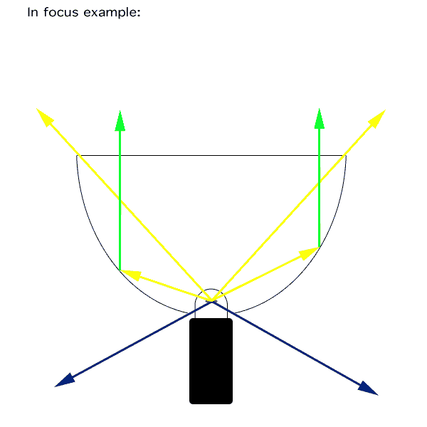
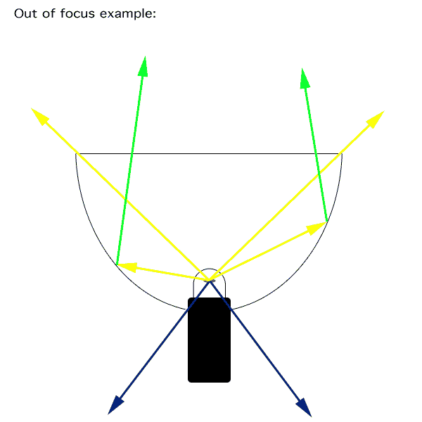
The filament of a bulb emits light in all directions. Different arrows in the diagrams represent different things happening.
The dark blue arrows, and all the area in-between them below the reflector opening, is a region of heavy light loss. As the position of the filament is moved up or down in the reflector, the angle of those dark blue arrows changes, and so does the amount of light headed into that "region."
This is not a region of 100% loss, because, as an observant user may notice, there are often materials in this region that will reflect some light, just not as well as a reflector. For example, the potting material in a bulb might be white in color, this would reflect some light, the PR base on many bulbs is a metallic material the lip around the top of the pot will reflect some light. People who use PR-bi-pin adapters may notice that the top plate of the adapter is a metallic material that should reflect some light. I do not know what the transmission efficiency of light emitted into the hole of the reflector could be estimated at. I could only guess perhaps that's it's between 20% and 50% depending on the particular flashlight in question.
The area between the long yellow arrows, is light that is not reflected in any way, it's only loss is whatever the lens absorbs, in the case of modern lenses, this can be anywhere between 1% and 10%, usually closer to the 1% if it's clean")
The area between the blue arrows and yellow arrows is light that is "captured" and reflected forward as part of the "beam."
You may notice, that as you defocus the bulb forward into the reflector, not only does the angle between the blue arrows shrink (reducing losses), the angle between the yellow arrows grows, this means more light is being transmitted out the front, without taking any reflector losses.
The only reason I have included this excursive in my "hypothesis" to to attempt to prove that the area between the 2 blue arrows is in fact a region of significant loss. Many people seem to be in denial that this region exists, I believe it does and I believe it is a factor that incandescent lights have to deal with.
-------------------------------------------
However: many things can be done to help reduce the effects of the evil blue arrow region!
As you may be able to deduce, a smaller hole in the bottom of the reflector (smallest possible for the bulb size), will increase the amount of light that hits the reflector, and reduce losses.
Installing a large bulb in a smaller reflector, will often cause more waste emissions, while installing a small bulb in a huge reflector, has the opposite effect. Here's some examples:
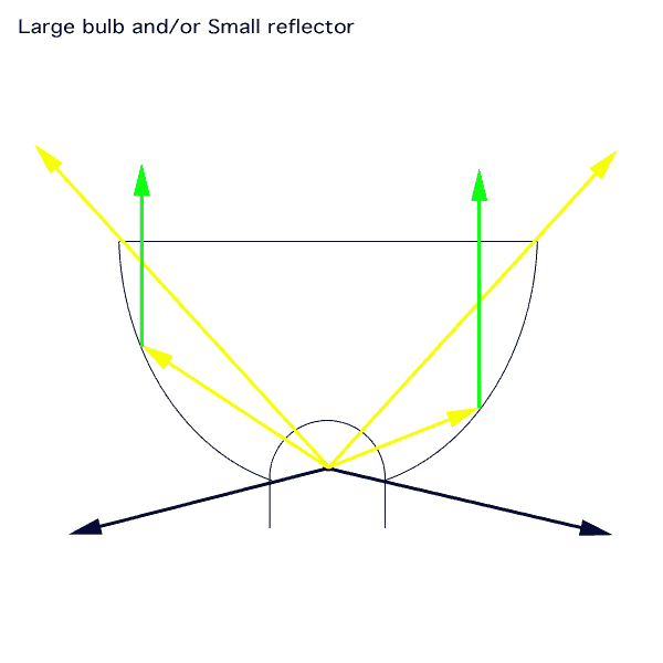
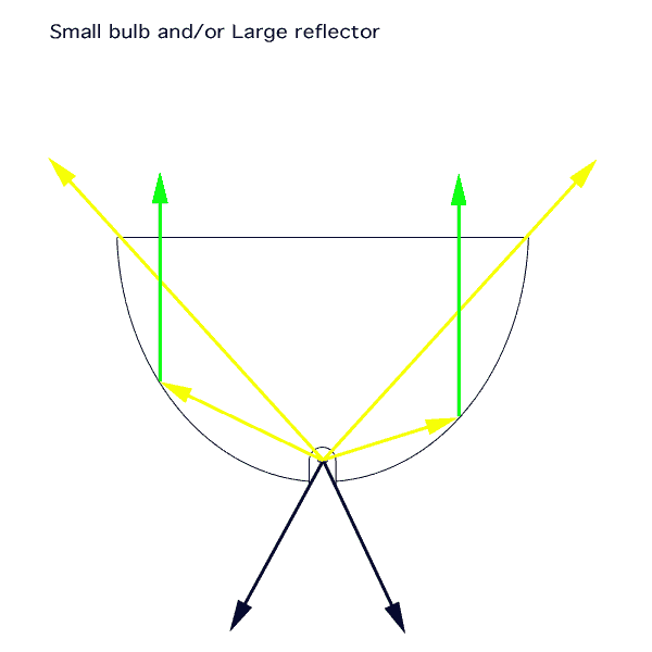
Ideally speaking, if a bi-pin bulb, with a reduced size "base" (many of them have a smaller rectangle shaped base that support the pins), were installed through a hole matching the size of that base through the top of the reflector, a great deal of losses could be eliminated. Good flashlight designs will have the smallest possible opening in the reflector for the bulb.
---------------------------------------------
Now I'd like to take a look at LEDs:
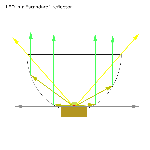
LEDs emit light on a "half sphere" and their lumen rating includes what is emitted on that half sphere. Imagine a plane intersecting the LED at it's base, nearly nearly 100% of the emissions occur above this plane. The grey double arrow line in the diagram above represents this cutoff point. There is no light going below this line, therefor, nothing is being lost "out the back" into an area of poor reflectivity.
Again, the long yellow arrows represent the cutoff for light that is being reflected, in-between those arrows, is light that is just coming out on a free ride, taking only a loss through the lens. Light emitted between the gray arrows and yellow arrows is light that must be reflected, and takes a loss due to reflector surfaces not being "perfect."
LEDs are different than filaments in many ways, not only do they emit all of their light on one side of a plane, they also do not emit light evenly in all directions above that plane. You can pull up a spec sheet on various types of LEDs available and they will almost always have a "radiation pattern" chart. Showing the intensity of light as measured from different angles in front of the LED. In many designs, the most intense light is found in the general range of about a ~90 degree angle (45 degrees either side of dead center), but dead center is not usually the strongest point. There are peaks in output at either side if dead center. So depending on the reflector design, deepness, shallowness, etc, or the type of emitter chosen (there are often different radiation patterns available), the amount of light that is reflected, compared with the amount of light that comes out as "spill" (free ride through lens, not reflected into the beam) can vary widely. Different designs will take a different amount of loss on the reflector depending on how much of the light is captured by the reflector compared with how much just comes out the front. Trading spill light for more throw can be accomplished by producing a deeper reflector, here's and example:
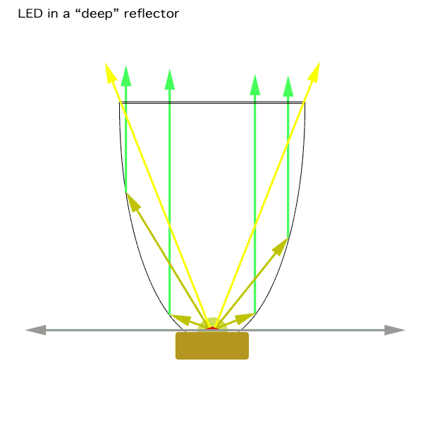
In the same way as we did with the incandescent examples we can compare the angles to get an idea of how much loss is taken in different parts of the emitted light. Comparing this example, to the LED in the "standard" reflector above, we see that the angle between the 2 long yellow arrows has decreased, while the angle between those yellow arrows and the grey ones has increased; This means that less light is coming out the front only taking lens losses, and more is taking reflector losses. But this type of design, would put more of the available light into the center beam, which will illuminate objects farther away and reduce the wide angle of the spill found in the "standard" reflector. The same design changes can be made for incandescent flashlights to achieve different beam intensity/spill tradeoffs.
--------------------------------------------
Discussion ideas/questions:
1. Do you believe that the region between the 2 blue arrows exists? explain.
2. What do you consider to be the generally accepted reflector surface efficiency? (not the reflector as a whole, just the surface of the reflector) I think between 70-85%
3. Assuming you are not in denial about the region between the 2 blue arrows: What do you feel is an acceptable general reflector efficiency to be assigned to the region between the blue arrows in most flashlight designs? Any ideas on how to maybe estimate this? I think between 20-50%
4. What transmission efficiency can be agreed upon to use as an "average" or "typical" in a broad discussion of flashlights? I like 95%, since 99% only applies to flashlights in a clean room with no dust or dirt on the lens, lol.
With some general consensus on these numbers, I could run some numbers and come to some sort of conclusion, or at least present some more ideas for fun.
5. Would "Sort of Conclusion" make a good name for a band? explain.
-------------------------------------------
Thank you for looking,
Eric
---------------------------------------
The generally accepted rule of thumb for converting to "torch" lumens in a flashlight is to simply multiply the bulb or emitter lumens by 0.65. This approach has been proven to be a very reasonable figure when discussing flashlights as a whole. There are obviously many variables involved, but the 0.65 rule seems to hold true quite frequently. However;
I have personally found myself questioning the validity of the 0.65 rule when applied to particular flashlight designs. There are 2 cases where I hypothesize that the 0.65 rule may be off by enough to warrant discussion:
1. In flashlights utilizing LEDs as their source of light.
2. In incandescent flashlights who's bulb envelope size to reflector size ratio is severely disproportionate to typical flashlight designs.
It should be noted, that I entirely realize, that this doesn't really matter much in the end. As it takes LARGE differences in output to change what useful applications a light has. Finding out that a light is 10-20% brighter or dimmer on paper based on a conclusion here will not have any realistic meaning to how useful the flashlight is and should not change anyones mind about what to buy. So with that in mind, lets keep any discussion on the subject friendly and positive because, it doesn't matter that much anyways.
------------------------------------------
First, a very simple test that almost any flashaholic can do themselves in about 30 seconds.
1. Go grab a maglite with the adjustable focus, a 2-3 cell stock one will work perfect.
2. place the flashlight on a flat surface pointed straight up onto the ceiling. in the middle of a room or hallway or bathroom, ideally.
3. Adjust the light to a tight focused beam. Observe illumination level of the room as a whole.
4. Defocus the beam, such that the bulb is moved forward in the reflector, (may need to double check which way the bulb is going by turning off the light and looking at the bulbs motion). Observe illumination level of the room as a whole.
5. repeat the focusing and defocusing and try to observe changes in the total illumination of the room you are in.
With my eyes, I can see a difference, when the beam is defocused with the bulb forward in the reflector, the room appears slightly more illuminated. This is substancial becuse in order to even be able to see a difference, the difference has to be noteworthy. Eyes are not very good light meters.
Here's some diagrams exploring what I believe is happening:
The filament of a bulb emits light in all directions. Different arrows in the diagrams represent different things happening.
The dark blue arrows, and all the area in-between them below the reflector opening, is a region of heavy light loss. As the position of the filament is moved up or down in the reflector, the angle of those dark blue arrows changes, and so does the amount of light headed into that "region."
This is not a region of 100% loss, because, as an observant user may notice, there are often materials in this region that will reflect some light, just not as well as a reflector. For example, the potting material in a bulb might be white in color, this would reflect some light, the PR base on many bulbs is a metallic material the lip around the top of the pot will reflect some light. People who use PR-bi-pin adapters may notice that the top plate of the adapter is a metallic material that should reflect some light. I do not know what the transmission efficiency of light emitted into the hole of the reflector could be estimated at. I could only guess perhaps that's it's between 20% and 50% depending on the particular flashlight in question.
The area between the long yellow arrows, is light that is not reflected in any way, it's only loss is whatever the lens absorbs, in the case of modern lenses, this can be anywhere between 1% and 10%, usually closer to the 1% if it's clean
The area between the blue arrows and yellow arrows is light that is "captured" and reflected forward as part of the "beam."
You may notice, that as you defocus the bulb forward into the reflector, not only does the angle between the blue arrows shrink (reducing losses), the angle between the yellow arrows grows, this means more light is being transmitted out the front, without taking any reflector losses.
The only reason I have included this excursive in my "hypothesis" to to attempt to prove that the area between the 2 blue arrows is in fact a region of significant loss. Many people seem to be in denial that this region exists, I believe it does and I believe it is a factor that incandescent lights have to deal with.
-------------------------------------------
However: many things can be done to help reduce the effects of the evil blue arrow region!
As you may be able to deduce, a smaller hole in the bottom of the reflector (smallest possible for the bulb size), will increase the amount of light that hits the reflector, and reduce losses.
Installing a large bulb in a smaller reflector, will often cause more waste emissions, while installing a small bulb in a huge reflector, has the opposite effect. Here's some examples:
Ideally speaking, if a bi-pin bulb, with a reduced size "base" (many of them have a smaller rectangle shaped base that support the pins), were installed through a hole matching the size of that base through the top of the reflector, a great deal of losses could be eliminated. Good flashlight designs will have the smallest possible opening in the reflector for the bulb.
---------------------------------------------
Now I'd like to take a look at LEDs:
LEDs emit light on a "half sphere" and their lumen rating includes what is emitted on that half sphere. Imagine a plane intersecting the LED at it's base, nearly nearly 100% of the emissions occur above this plane. The grey double arrow line in the diagram above represents this cutoff point. There is no light going below this line, therefor, nothing is being lost "out the back" into an area of poor reflectivity.
Again, the long yellow arrows represent the cutoff for light that is being reflected, in-between those arrows, is light that is just coming out on a free ride, taking only a loss through the lens. Light emitted between the gray arrows and yellow arrows is light that must be reflected, and takes a loss due to reflector surfaces not being "perfect."
LEDs are different than filaments in many ways, not only do they emit all of their light on one side of a plane, they also do not emit light evenly in all directions above that plane. You can pull up a spec sheet on various types of LEDs available and they will almost always have a "radiation pattern" chart. Showing the intensity of light as measured from different angles in front of the LED. In many designs, the most intense light is found in the general range of about a ~90 degree angle (45 degrees either side of dead center), but dead center is not usually the strongest point. There are peaks in output at either side if dead center. So depending on the reflector design, deepness, shallowness, etc, or the type of emitter chosen (there are often different radiation patterns available), the amount of light that is reflected, compared with the amount of light that comes out as "spill" (free ride through lens, not reflected into the beam) can vary widely. Different designs will take a different amount of loss on the reflector depending on how much of the light is captured by the reflector compared with how much just comes out the front. Trading spill light for more throw can be accomplished by producing a deeper reflector, here's and example:
In the same way as we did with the incandescent examples we can compare the angles to get an idea of how much loss is taken in different parts of the emitted light. Comparing this example, to the LED in the "standard" reflector above, we see that the angle between the 2 long yellow arrows has decreased, while the angle between those yellow arrows and the grey ones has increased; This means that less light is coming out the front only taking lens losses, and more is taking reflector losses. But this type of design, would put more of the available light into the center beam, which will illuminate objects farther away and reduce the wide angle of the spill found in the "standard" reflector. The same design changes can be made for incandescent flashlights to achieve different beam intensity/spill tradeoffs.
--------------------------------------------
Discussion ideas/questions:
1. Do you believe that the region between the 2 blue arrows exists? explain.
2. What do you consider to be the generally accepted reflector surface efficiency? (not the reflector as a whole, just the surface of the reflector) I think between 70-85%
3. Assuming you are not in denial about the region between the 2 blue arrows: What do you feel is an acceptable general reflector efficiency to be assigned to the region between the blue arrows in most flashlight designs? Any ideas on how to maybe estimate this? I think between 20-50%
4. What transmission efficiency can be agreed upon to use as an "average" or "typical" in a broad discussion of flashlights? I like 95%, since 99% only applies to flashlights in a clean room with no dust or dirt on the lens, lol.
With some general consensus on these numbers, I could run some numbers and come to some sort of conclusion, or at least present some more ideas for fun.
5. Would "Sort of Conclusion" make a good name for a band? explain.
-------------------------------------------
Thank you for looking,
Eric

 Alas, it was not. OK, I'm pushing the envelope on my style of humor.