hipFlex

georges80

Flashlight Enthusiast
Joined
Oct 23, 2002
Messages
1,262
Location
Sunnyvale, CA
Might as well start a new thread for the hi power Flex proto.

hflex2.jpg


The thermal pad material that I used is available from Mouser. About US$22 for a sheet, so rather spendy, but given how well it works and how little is typically needed I think it is reasonable value and useful to have in a modder's drawer.

http://www.mouser.com/Search/Refine.aspx?Keyword=861-TGF150D

I am very impressed how well the material works, it is very pliable and conforms well to the surface it is on. It is not sticky, but it acts as if it is tacky and if pressed between a heatsink and Star etc. it does 'hold' the item in place. Obviously some further mechanical attachment method would be highly advisable. Mouser also has a few different grades available (price varies depending on thermal conductivity).

hipFlex is at the proto stage right now, I am on the 2nd revision, mainly changes in layout and power FET. Rev2 appears to work very well, I ran it 2 hours with no airflow, just mounted on the aluminium using the thermal pad material and it never got more than warm (maybe 30C with 20C ambient). The 3 P7's did get hot (~28W input power to them) - well, the larger chunk of aluminium they were on got hot and so had a fan keeping things stable.

The design of the board has two mounting holes to provide a way to 'squeeze' the thermal pad material between the heatsink and the bottom of the PCB which is the thermal interface (lots of thermal vias from the key 'hot' components). The board only has components on the top side to make it easier to mount the entire bottom of the board to a heatsink, though only the right 1/2 (approx) needs to be. The board is 1.4" in diameter, so not tiny, but then a multi P7 (or MCE) light is not going to be tiny anyway.

At this time I plan to support 4 current tables, 1A, 1.5A, 2A and 2.8A). For <1A just use a bFlex or nFlex.

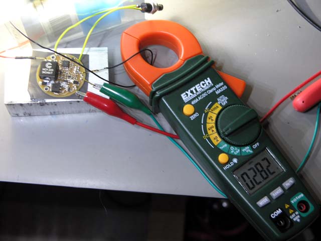
Initial efficiency measurement with ~16V in and ~10V out (3 x P7) at 2.8A out shows just over 92% which is pretty good in my books.

The hipFlex has reverse polarity protection, temperature sensing, input voltage sensing and essentially the entire UI-uni firmware base that is on the other Flex drivers - so nothing new to learn there.

There is more testing to do and tuning of current tables/levels before I commit to do a production run of boards.

I'm also trying to gauge the interest in such a driver. My aim is to price it ~ $35 and provide a piece of the thermal pad material.

cheers,
george.
 

hootsmon

Newly Enlightened
Joined
Sep 28, 2008
Messages
18
George, that's awesome. I'm sure there's lots of crazy DIYers just drooling at the possibilities of something like this.
:twothumbs
 

Hack On Wheels

Enlightened
Joined
Nov 4, 2007
Messages
774
Location
Canada
Nice work! :)

A bit of a shame about the size though... it sounds like it should be flush mounted to a surface? I've got a design based around the MaxFlex, but this could possibly work if fitted on a diagonal and I guess it would need to be epoxied to some kind of bracket. If the Boomerang reflectors work out well for the MCE and the P7, then smaller builds will be possible. If not, then this driver will fit very nicely in the same body as a double of triple MCE setup.

I can't wait until this is released! The real question is, what will troutie do with it? :p
 

trout

Enlightened
Joined
Nov 29, 2007
Messages
425
Location
yorkshire / England
:goodjob: George fantastic news :grouphug: From the crazy trout

Size is near perfect for a D cell Maglite tube

I like the single sided design with fixing holes .

What will be the max voltages it can take and deliver.

Thank you George will it be before :santa: pays a visit
 

georges80

Flashlight Enthusiast
Joined
Oct 23, 2002
Messages
1,262
Location
Sunnyvale, CA
:goodjob: George fantastic news :grouphug: From the crazy trout

Size is near perfect for a D cell Maglite tube

I like the single sided design with fixing holes .

What will be the max voltages it can take and deliver.

Thank you George will it be before :santa: pays a visit

Max input voltage is 24V. It is a buck converter so as long as the input is say 2V above the output (more testing to do) it will regulate.

I need to do more thermal testing to see how it handles 4 P7's, 5 P7's or even 6 P7's.

Given it's already handling ~28W with 3 P7's that's already a lot of power going through the board and one reason for its size. I chose the best FET I could spec for the power conversion area and the inductor is more than up to the job.

The single sided design is specifically to allow a good thermal path for the driver to the heatsink. Even at say 92% efficiency, 8% heat loss with 28W output means about 2.3W that is being dissipated in the driver. Move up to more P7's (at 2.8A) and you can see we need a decent thermal path (and component ratings) to be able to handle the heat.

The output stage is rated to 25V (so no danger if open circuit occurs, given the max input voltage is 24V).

I doubt very much it will be in time for :santa: at this point - I need to finish testing the firmware and current tables before I get production boards runs and that takes time. I'll probably look at doing a small pre-production run to get some into the field and have them beaten on before running a large batch.

At these power levels thermal management of the LEDs and driver requires more attention than just putting a dab off AA epoxy here & there :)

cheers,
george.
 

trout

Enlightened
Joined
Nov 29, 2007
Messages
425
Location
yorkshire / England
Thanks for all that George
Sounds Ace and I am sure a lot of the techie guys will be planning
outrageous builds out there .

If there is a list for buying one to crash test please put me on it
 

Tidra

Enlightened
Joined
Nov 10, 2006
Messages
211
Location
Slovenia - EU
Great news, count me in,...
just try to stay on the size that could go in to the Mag D,...

Thank you
Iztok
 

imageicon

Newly Enlightened
Joined
Aug 21, 2007
Messages
40
that is great news finally a feasible way to run several multi emitter chips...
 

Cat-Man-Do

Newly Enlightened
Joined
Nov 13, 2008
Messages
9
Hipflex (?)....Is it made yet, is it made yet, is it made yet...:D
( Note: this is my first post on CPF. I'm just posting here to make Troutie and the other DIY'ers on MTBreview forum happy. Besides, without a good driver, no ones going to be able to get the maximum punch from the new P-7's and MC-E's for their multi-builds )
 

ledgend lights

Newly Enlightened
Joined
Oct 16, 2008
Messages
29
George

That sounds great, not that we'd expect anything less from you.

Put me down for a pre-production one to test.

Mark
 

georges80

Flashlight Enthusiast
Joined
Oct 23, 2002
Messages
1,262
Location
Sunnyvale, CA
I've just run a 5 x P7 load at 2.8A for over 40 minutes and the driver was very happy. Fan cooling of the LEDs of course :)

Ambient at 25C and the driver was at 40C after 40 minutes mounted to a chunk of aluminium with the thermal pad material.

With 19V input and ~17V output at 2.8A I calculate 95% efficiency through the driver board. Around 47W pumping through the driver - pretty impressive imho.

cheers,
george.
 

bluecrow76

Enlightened
Joined
Jul 10, 2006
Messages
638
Location
Tiger Town
This is great news George! I'm having visions of one of these in my barbolight host with some P7's... if I can just figure out how to introduce a switch into the mix.... hall effect switch or reed switch???
 
Last edited:

emu26

Newly Enlightened
Joined
Sep 24, 2008
Messages
2
Fantastic George, but where was it a month ago when I ordered my maxflex?

Can't wait for this one
 

georges80

Flashlight Enthusiast
Joined
Oct 23, 2002
Messages
1,262
Location
Sunnyvale, CA
After more testing, things look good on the hipFlex front so I've ordered a small run of production PCB's to be made. Should have them in hand within 2 weeks.

I ordered parts to build up 10 pre-production units for some field beating/testing.

I don't take pre-pays, never have, never will.

cheers,
george.
 

herulach

Enlightened
Joined
Jul 13, 2008
Messages
244
George, that looks awesome. What kind of headroom do you need on Vbatt vs, Vf? Currently re-doing my lights to a twin p7, would like to build the potential to swap this in at the start.
 

georges80

Flashlight Enthusiast
Joined
Oct 23, 2002
Messages
1,262
Location
Sunnyvale, CA
George, that looks awesome. What kind of headroom do you need on Vbatt vs, Vf? Currently re-doing my lights to a twin p7, would like to build the potential to swap this in at the start.

Very little headroom, I just ran a test.

3 series connected P7's at 2.8A drive current.

Total Vf of the 3 P7's is 10.26V at 2.8A and was in regulation until Vin (measured right at the input of the driver) dropped to 10.89V.

The prototype uses a schottky diode for reverse polarity protection and I measure 0.268V across it at close to 2.8A input current.

The production boards will use a power FET instead (like bFlex) and it should only introduce around 0.1V drop at 2.8A input.

10.89 - 10.26 - (0.268 - 0.1) = 0.46V

So, it would appear the production hipFlex (for 3 P7's) will need about 0.5V of headroom at 2.8A output which imho is quite impressive at that current level!

Ok, just ran 2 P7's at 2.8A.

2 P7's Vf = 6.8V (at 2.8A). Was in regulation until the input dropped to 7.41V

So, again:

7.41 - 6.8 - (0.268 - 0.1) = 0.44V

So, it appears that the production version would be in regulation with 2 P7's with 0.5V of headroom at 2.8A.

Neato! :)


Oh, one thing, the driver needs a minimum of 4.5V to operate, so this will not be a single P7/single Li-ion solution...

cheers,
george.
 
Last edited:
Top