StefanFS
Flashlight Enthusiast
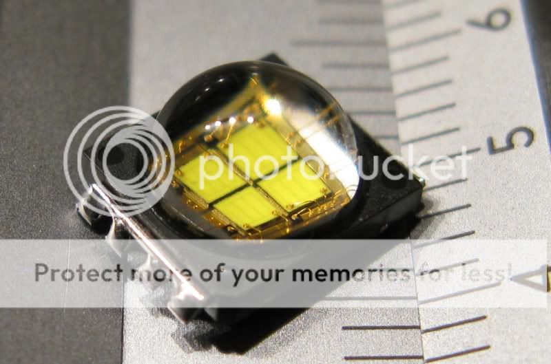
What you need for this project. A driver sandwich (see below), one CREE MC-E M bin emitter, one heatsink, some 0.3 mm silver wire or copper wire and some tools.
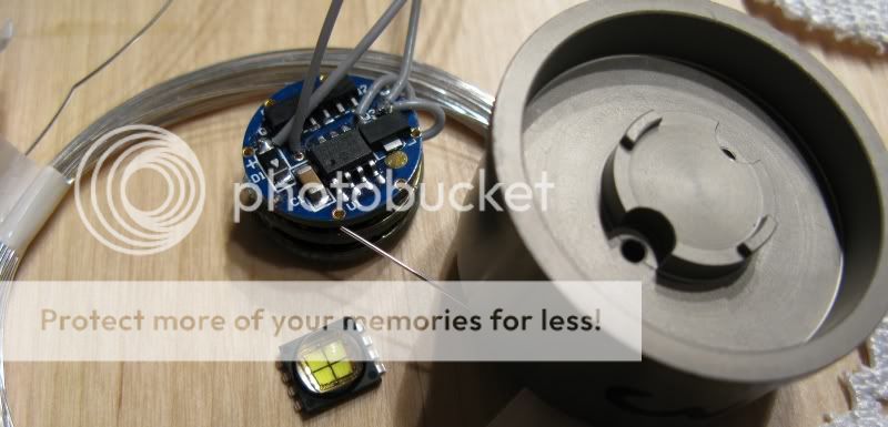
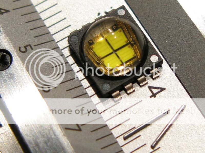
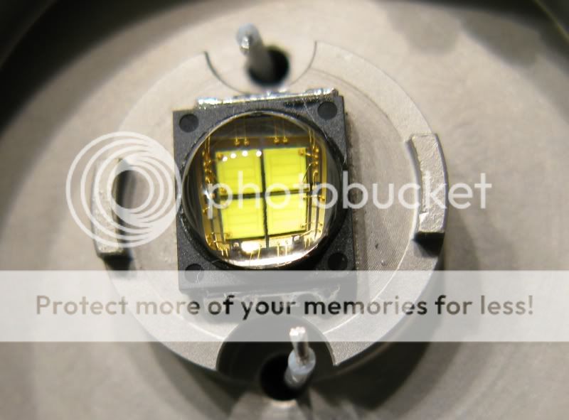
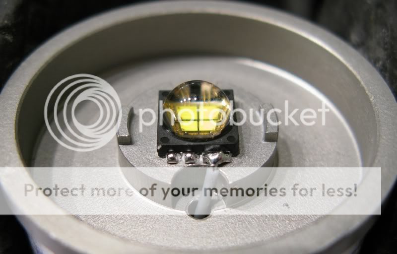
Preparing the emitter for parallell operation means you have to use a bridge to connect all the legs/connections on the emitter. The side with a cut corner is positive. Silver wires beneath the MC-E.
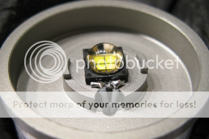
Pretinning the emitter legs..
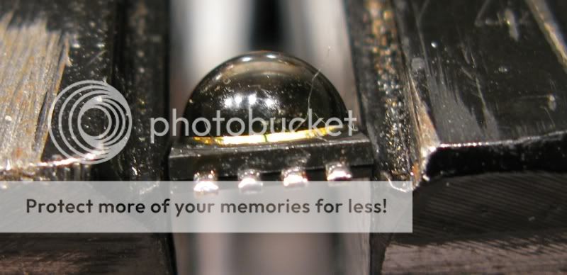
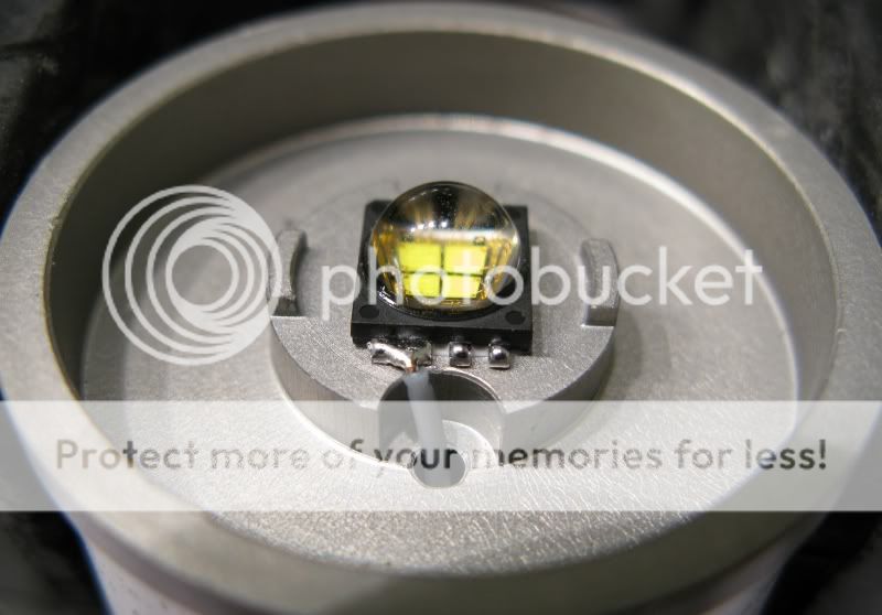
Silver wire soldered to the emitter legs, it is difficult to get a good looking result. A steady hand and a fine tipped iron are bonuses in this step.
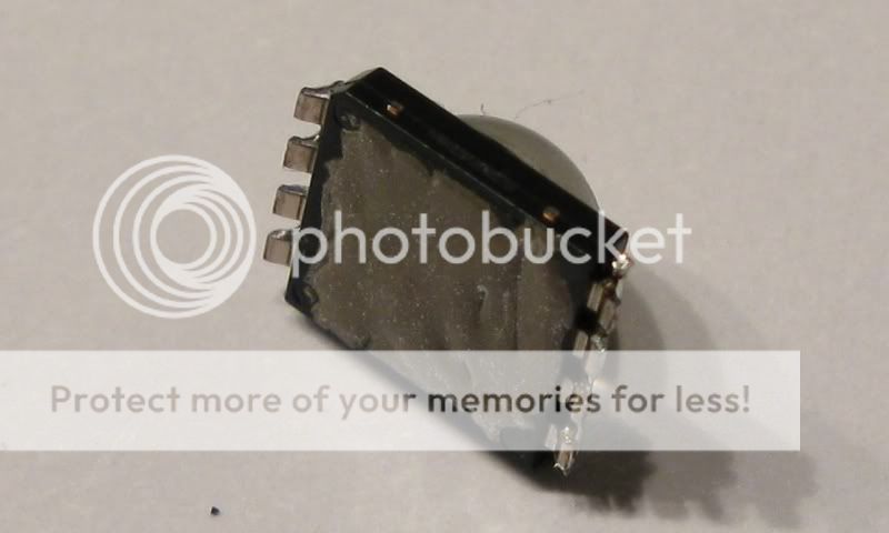
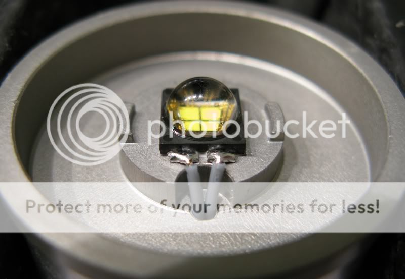
An exceptionally thin layer of Arctic silver epoxy to get a good thermal bond to the heatsink. The epoxy need to cure, best to leave it for 24 hours.
I simply glue the driver sandwich to the bottom of the heatsink and trim the leads to fit. No, that's not a problem with this solution, the driver does not get hot and if the heatsink get hot the led will fail before the driver even get close to overheating.
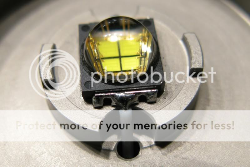
Soldering the 26 AWG teflon wire from the driver to the parallell prepared emitter legs.
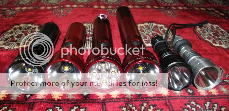
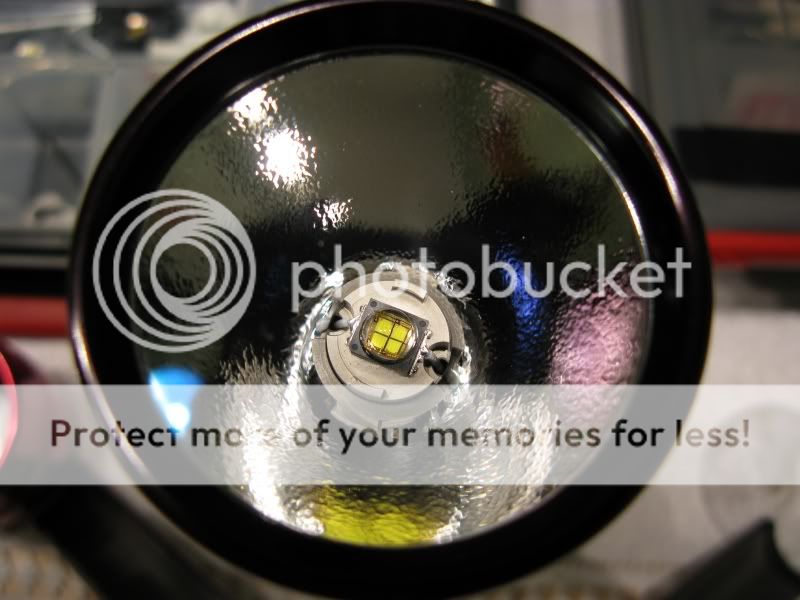
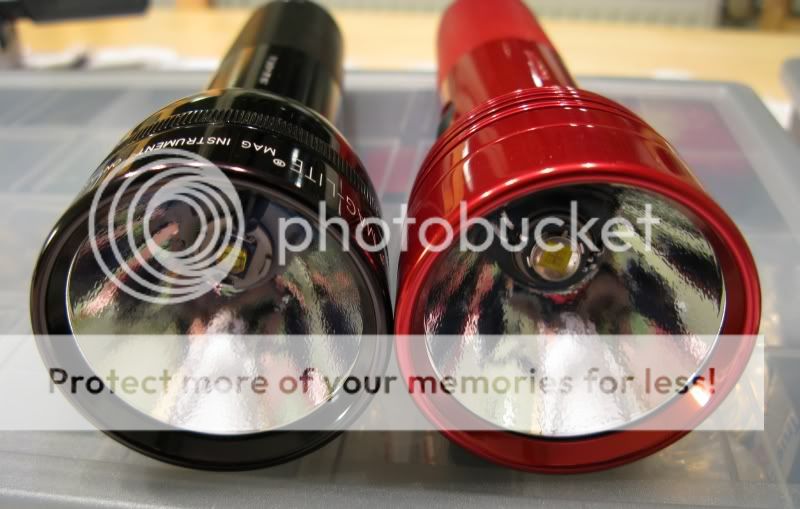
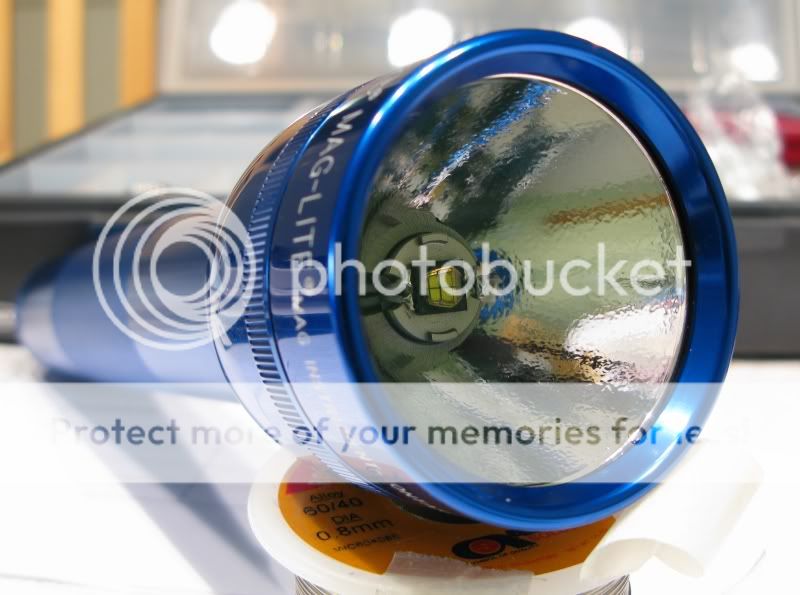
The finished result. It's a bored out 1D Maglite with UCL-glass and an OP alu reflector. Running on 1 D LiION. The beam distribution is almost identical to my SSC P7 DSWOI Mags with OP reflectors, visually that is. The MC-E M-bin Mag has less throw but more intense spill, spill is 15-20 % brighter and throw is ~15-20% less. The parallell solution seem to work very well with the MC-E in a Mag with a good heatsink. I plan on doing a 2 Serial-2 Parallel in a 2D Mag, with AMC 7135 based drivers and 2 D LiION cell or 6 AA eneloop. I'll post that in this thread.
How to build a high quality, low cost, regulated 3 Ampere driver for your SSC P7 or parallell CREE MC-E Maglite
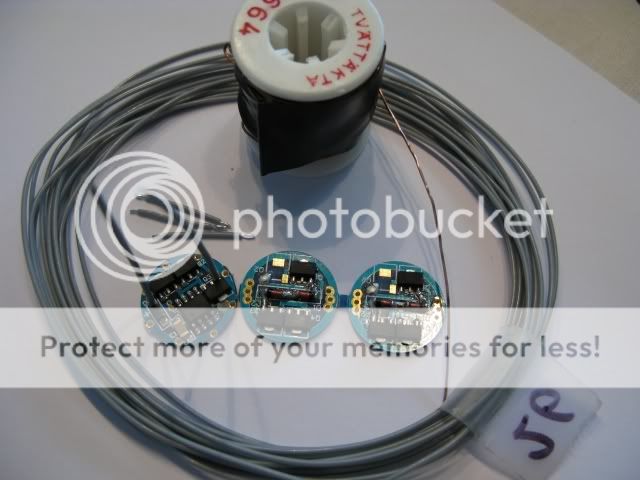
This is what you need. Two 1A simple AMC7135 drivers (I buy the 1400mA kind and desolder the last chip at Q2 to make it ~1A) and one 1A AMC7135 multimode driver to control them. Some copper wire, teflon wire 24 or 26 gauge. Three connections are needed between the multimode and the slave sandwich, ~15 mm each. Two 5-7 mm pieces of copper wire to connect battery negative and battery positive between boards on the slave sandwich. One 10 mm piece of teflon wire to connect led negative between boards on the slave sandwich. Two pieces of 20-30 mm teflon wire for connection to the led from the multimode board.
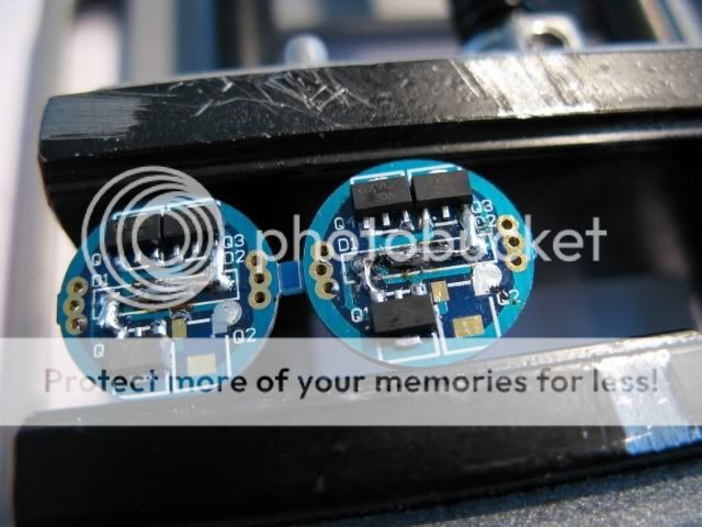
Preparing the boards for the slave sandwich. Removing diodes and making sure connections are made between all AMC7135 chips with solder.
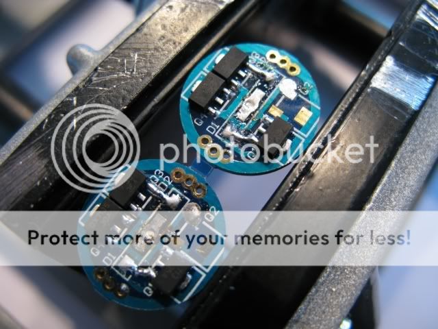
Soldering some copper wire jumpers in place of the diodes.
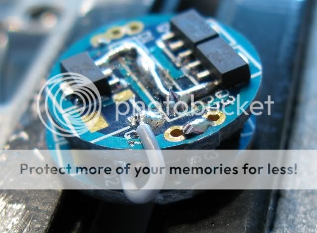
Making the sandwich. Battery negative is connnected on the edge with copper wire soldered between the boards, the ring around the boards. Not seen is a similar piece of copper wire going from center positive to the other boards center postive (if you miss this it will only give you 2.0A). A short piece of teflon wire going from led negative to led negative.
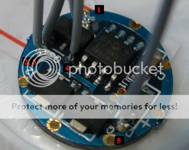
Preparing the multimode driver.
1 will go to battery negative on the slave sandwich.
2 will go to led negative on the slave sandwich.
3 will go to emitter negative.
4 will go to center positive on the top board of the slave sandwich.
5 is going to led positive.
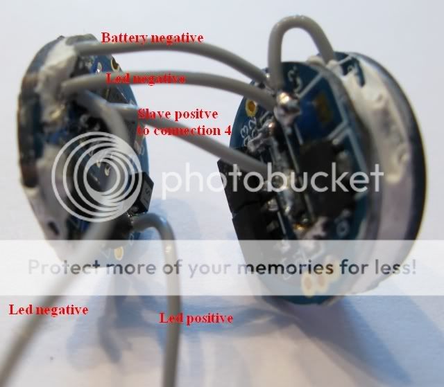
Battery negative and positive connect to the underside of this driver,
negative to the ring and positive to the center.
To illustrate the connections.
Battery options are 1D or 1C or 1 x 18650 LiION, 3 x D-size NiMH 9000 mAh and up or 4 C/AA size NiMH. It's even possible to use one protected LiION and one NiMH cell as long as the NiMH cell have considerably higher capacity compared with the LiION cell. Everything goes with this driver as long as you keep it under 6V. Preferably under 5V for most of the runtime if that's possible.
Driver bords used can be found in a lot of places, two that are familiar to CPF are DX & KaiDomain:
2-Level: http://www.kaidomain.com/ProductDetails.aspx?ProductId=1801
16-Mode: http://www.dealextreme.com/details.dx/sku.7612
5-Mode: http://www.dealextreme.com/details.dx/sku.6190
1400 mA boards: http://www.dealextreme.com/details.dx/sku.1886
A 2S 2P solution for 2 LiION cells or 6 AA.
The basis for this mod. User downloads excellent 2S2P solution based on AMC7135 drivers (pic borrowed from dowloads thread on the subject):
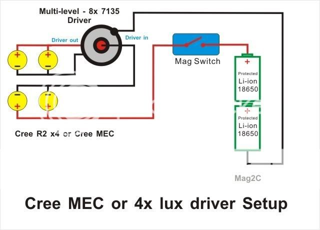
It differs from the diagram above in that my driver output ~1700 mA which will drive each dice at ~800-850 mA. See this thread for that discourse:
https://www.candlepowerforums.com/threads/201392
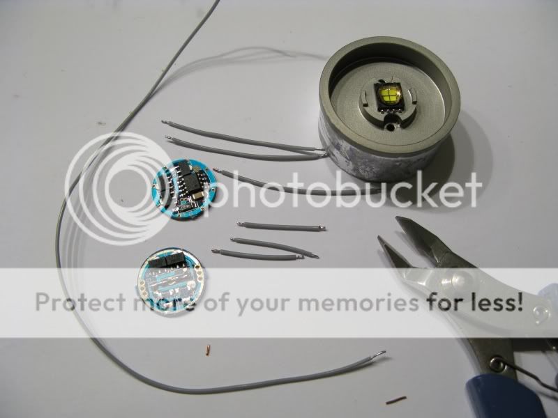
The MC-E mounted on a heatsink (for SSC P7 by user H22A), one 2 level 1000 mA AMC7135 based multimode driver and the 700 mA AMC7135 it uses as an extension/slave board. The teflon 26 AWG wire used is shown. The long piece is for switch positive to the first set of positive legs on the emitter, more on that below. The three short pieces are for connecting the boards and the three medium long ones are going to the emitter. The respective lenghts I used: 20 mm, 50 mm and 100 mm.
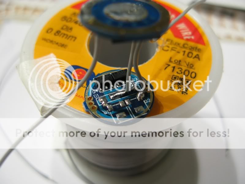
How the extension/slave board should look.
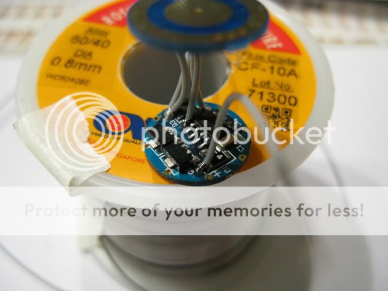
With connections to the multimode driver.
The first connection to the emitter, this is from switch positive on the emitters positive side, see the cut corner at low right. I simply solder the wire between dice 1 & 2's positive contacts and let the solder bridge the connection.
Solder point 2 on the positive side goes to the driver positive out to emitter, the wire normally going from a driver to led positive.
First solder point on the emitter negative side. this is opposite the first solder point on the positive side. This one goes to the driver positive in (battery in) , where the wire from the switch module positive would go normally.
Second solder point on the negative side connects the driver led negative to the emitter.
A really wonderful result. It works great and looks even better. With the 2S2P driver two LiION cells or 6 AA eneloop in a cell holder are the best choices. Max 8.4 Volt.
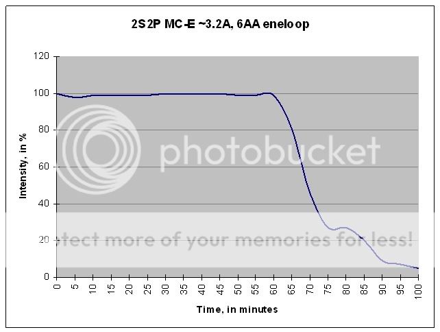
A runtime with 6AA eneloop. This is really good, especially considering it's mildly overdriven and each die get slightly over 800 mA. Going on experience from my SSC P7 Mag builds I'd venture to say that runtime would double with 2 x 5 Ah LiION D-size cells, instead of eneloops in a holder.
I used one 1400 mA AMC7135 board that I stripped two AMC chips from according to the pics above. The simple AMC7135 drivers below 1400 mA being sold now are different in design, they are based on the multimode pcb.
Stefan
Preparing the emitter for parallell operation means you have to use a bridge to connect all the legs/connections on the emitter. The side with a cut corner is positive. Silver wires beneath the MC-E.
Pretinning the emitter legs..
Silver wire soldered to the emitter legs, it is difficult to get a good looking result. A steady hand and a fine tipped iron are bonuses in this step.
An exceptionally thin layer of Arctic silver epoxy to get a good thermal bond to the heatsink. The epoxy need to cure, best to leave it for 24 hours.
I simply glue the driver sandwich to the bottom of the heatsink and trim the leads to fit. No, that's not a problem with this solution, the driver does not get hot and if the heatsink get hot the led will fail before the driver even get close to overheating.
Soldering the 26 AWG teflon wire from the driver to the parallell prepared emitter legs.
The finished result. It's a bored out 1D Maglite with UCL-glass and an OP alu reflector. Running on 1 D LiION. The beam distribution is almost identical to my SSC P7 DSWOI Mags with OP reflectors, visually that is. The MC-E M-bin Mag has less throw but more intense spill, spill is 15-20 % brighter and throw is ~15-20% less. The parallell solution seem to work very well with the MC-E in a Mag with a good heatsink. I plan on doing a 2 Serial-2 Parallel in a 2D Mag, with AMC 7135 based drivers and 2 D LiION cell or 6 AA eneloop. I'll post that in this thread.
------------------------------------------------------------------------
How to build a high quality, low cost, regulated 3 Ampere driver for your SSC P7 or parallell CREE MC-E Maglite
This is what you need. Two 1A simple AMC7135 drivers (I buy the 1400mA kind and desolder the last chip at Q2 to make it ~1A) and one 1A AMC7135 multimode driver to control them. Some copper wire, teflon wire 24 or 26 gauge. Three connections are needed between the multimode and the slave sandwich, ~15 mm each. Two 5-7 mm pieces of copper wire to connect battery negative and battery positive between boards on the slave sandwich. One 10 mm piece of teflon wire to connect led negative between boards on the slave sandwich. Two pieces of 20-30 mm teflon wire for connection to the led from the multimode board.
Preparing the boards for the slave sandwich. Removing diodes and making sure connections are made between all AMC7135 chips with solder.
Soldering some copper wire jumpers in place of the diodes.
Making the sandwich. Battery negative is connnected on the edge with copper wire soldered between the boards, the ring around the boards. Not seen is a similar piece of copper wire going from center positive to the other boards center postive (if you miss this it will only give you 2.0A). A short piece of teflon wire going from led negative to led negative.
Preparing the multimode driver.
1 will go to battery negative on the slave sandwich.
2 will go to led negative on the slave sandwich.
3 will go to emitter negative.
4 will go to center positive on the top board of the slave sandwich.
5 is going to led positive.
Battery negative and positive connect to the underside of this driver,
negative to the ring and positive to the center.
To illustrate the connections.
Battery options are 1D or 1C or 1 x 18650 LiION, 3 x D-size NiMH 9000 mAh and up or 4 C/AA size NiMH. It's even possible to use one protected LiION and one NiMH cell as long as the NiMH cell have considerably higher capacity compared with the LiION cell. Everything goes with this driver as long as you keep it under 6V. Preferably under 5V for most of the runtime if that's possible.
Driver bords used can be found in a lot of places, two that are familiar to CPF are DX & KaiDomain:
2-Level: http://www.kaidomain.com/ProductDetails.aspx?ProductId=1801
16-Mode: http://www.dealextreme.com/details.dx/sku.7612
5-Mode: http://www.dealextreme.com/details.dx/sku.6190
1400 mA boards: http://www.dealextreme.com/details.dx/sku.1886
--------------------------------------------------------------------------------------------------------------------------------
--------------------------------------------------------------------------------------------------------------------------------
A 2S 2P solution for 2 LiION cells or 6 AA.
The basis for this mod. User downloads excellent 2S2P solution based on AMC7135 drivers (pic borrowed from dowloads thread on the subject):
It differs from the diagram above in that my driver output ~1700 mA which will drive each dice at ~800-850 mA. See this thread for that discourse:
https://www.candlepowerforums.com/threads/201392
The MC-E mounted on a heatsink (for SSC P7 by user H22A), one 2 level 1000 mA AMC7135 based multimode driver and the 700 mA AMC7135 it uses as an extension/slave board. The teflon 26 AWG wire used is shown. The long piece is for switch positive to the first set of positive legs on the emitter, more on that below. The three short pieces are for connecting the boards and the three medium long ones are going to the emitter. The respective lenghts I used: 20 mm, 50 mm and 100 mm.
How the extension/slave board should look.
With connections to the multimode driver.
The first connection to the emitter, this is from switch positive on the emitters positive side, see the cut corner at low right. I simply solder the wire between dice 1 & 2's positive contacts and let the solder bridge the connection.
Solder point 2 on the positive side goes to the driver positive out to emitter, the wire normally going from a driver to led positive.
First solder point on the emitter negative side. this is opposite the first solder point on the positive side. This one goes to the driver positive in (battery in) , where the wire from the switch module positive would go normally.
Second solder point on the negative side connects the driver led negative to the emitter.
A really wonderful result. It works great and looks even better. With the 2S2P driver two LiION cells or 6 AA eneloop in a cell holder are the best choices. Max 8.4 Volt.
A runtime with 6AA eneloop. This is really good, especially considering it's mildly overdriven and each die get slightly over 800 mA. Going on experience from my SSC P7 Mag builds I'd venture to say that runtime would double with 2 x 5 Ah LiION D-size cells, instead of eneloops in a holder.
I used one 1400 mA AMC7135 board that I stripped two AMC chips from according to the pics above. The simple AMC7135 drivers below 1400 mA being sold now are different in design, they are based on the multimode pcb.
Stefan
Last edited: