Hey folks!
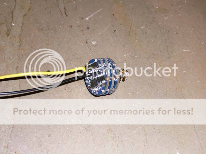
My P7 arrived just the other day :twothumbs, unfortunately they didn't ship the drivers I were to be using. I'll be using one 5 mode driver board and two slaves in a setup near identical to the one which NetKidz proposed(link follows).
https://www.candlepowerforums.com/threads/192677
In the meantime seeing as I don't have any drivers. I decided to have a fiddle with the P7 in a direct drive setup. To keep it cool I have used a spare Fan/Heatsink from a Core2 Duo, flipped upside down, which is running off of a modified computer power supply.
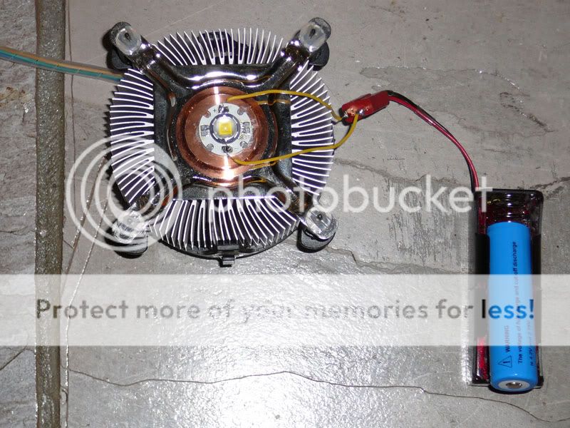
As many of you will be aware, there aren't any battery holders for the 18650's, however as I have done, you may be able to construct one by cutting up two single c-cell battery snaps, and then gluing both portions together using 3 pieces of perspex cut to appropriate dimensions(the perspex is about 3mm thick - I haven't actually measured it). The battery fits perfectly .
.
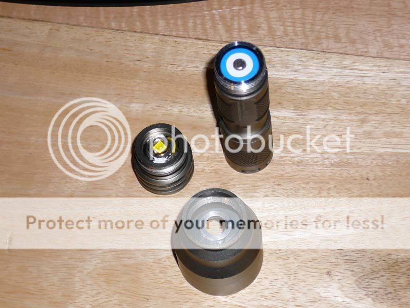
Anyhow, the P7 has been stuck to the copper section of the Heatsink with Arctic Silver thermal compound.
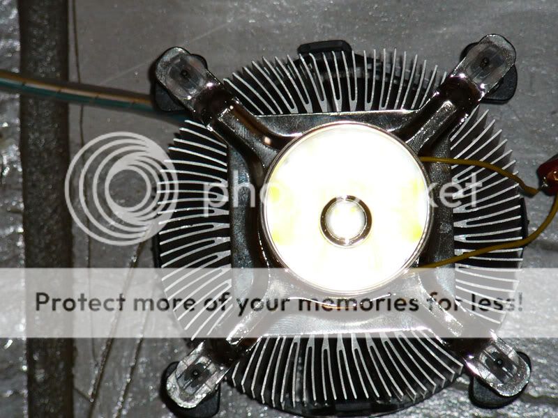
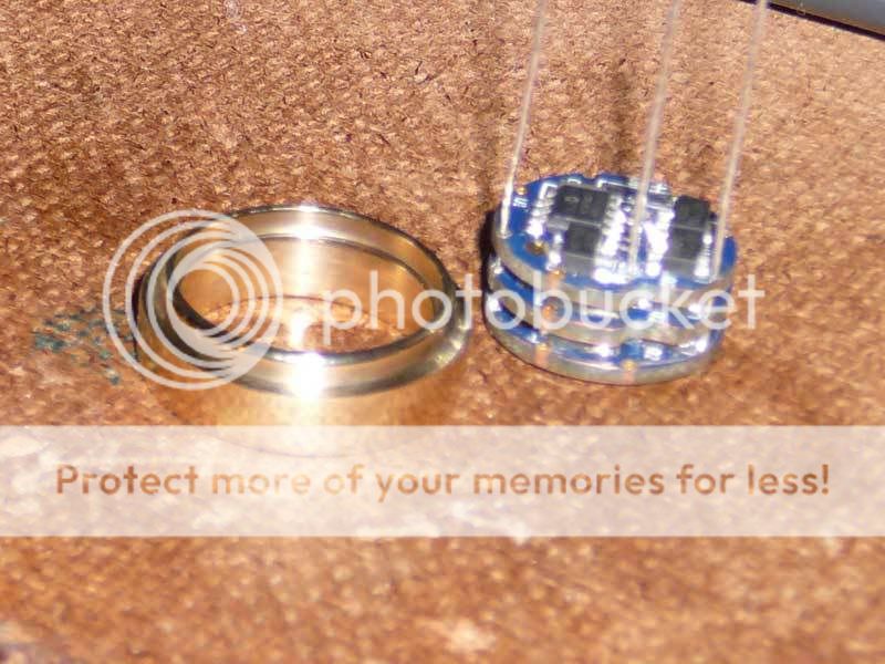
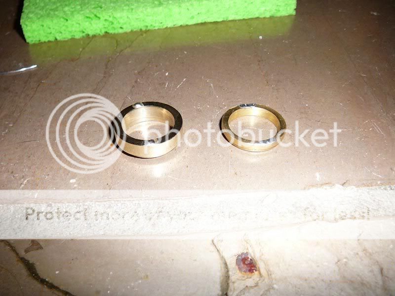
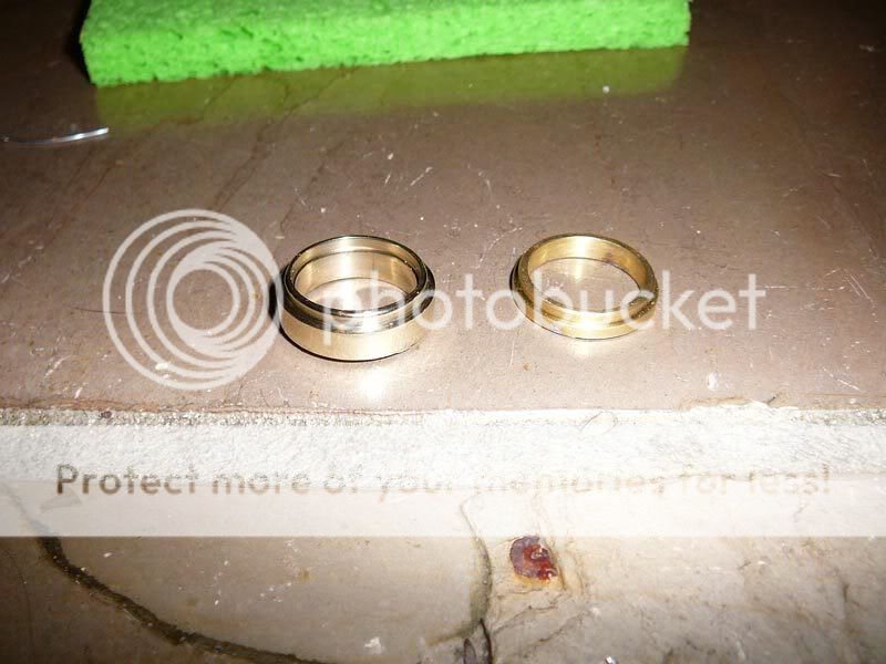
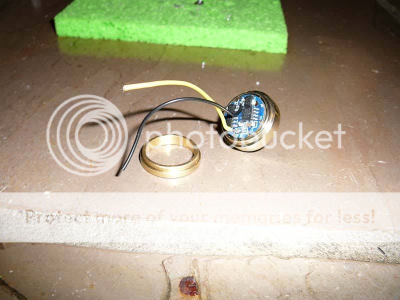
With my modified reflector resting atop of the LED.
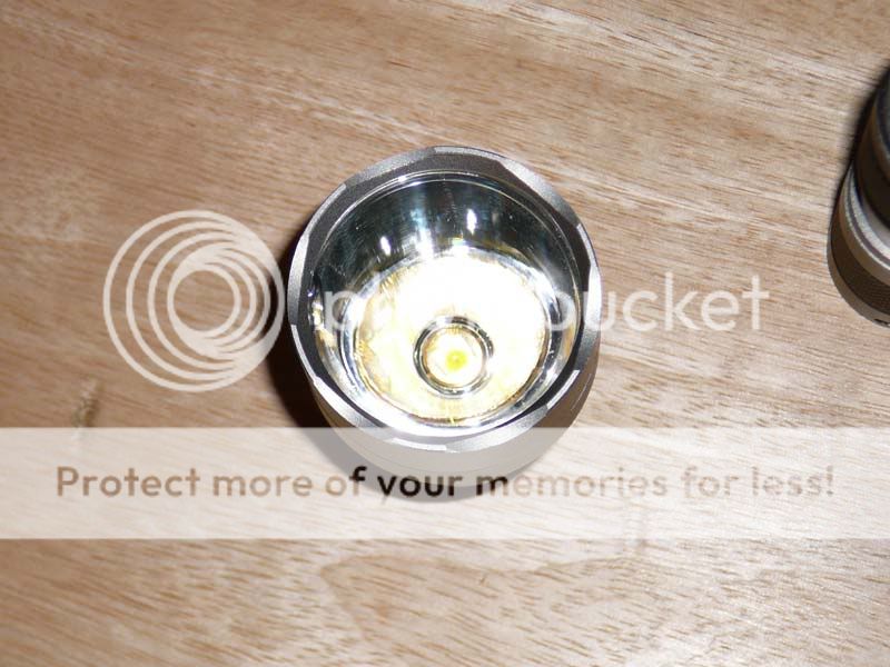
To increase the diameter of the hole which was originally existant for the Cree XR-E I used a tapered grinding stone and slowly increased the diameter. After which i used a thin cylindrical sanding attachment to increase the hole further and faster(the tapered grinding stone was beginning to "stick"). Unfortunately some of the sanding had the effect of giving the inner-most region of the reflector a sandblasting with offcuts. However the effect of this is barely noticeable and probably adds toward reducing the slight donut hole.
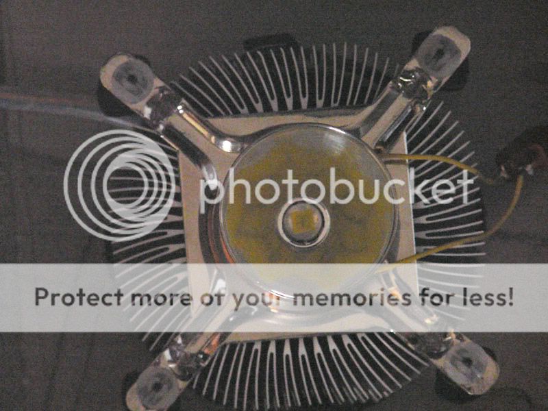
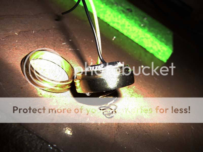
Another shot, this time without the flash(I had to adjust the brightness/contrast a little so it's a bit grainy).
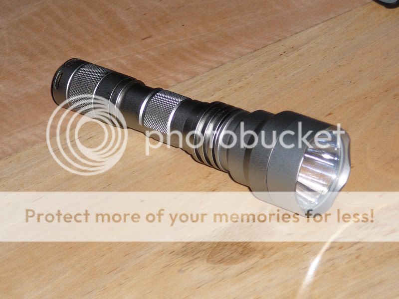
Anyhow, here are the pics you guys are after!
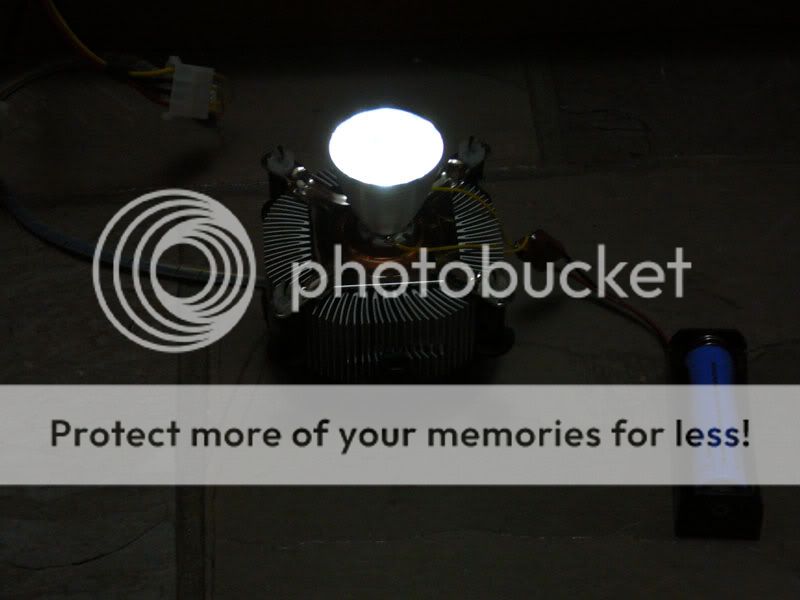

Unfortunately due to nature of the setup this is the only beamshot I have. There will be more in the near future, I promise!(You can't see it in this picture, but there is a slight donut hole in the centre)
One thing I have noticed is that the globe only seems to be running at about 1amp(the current drops slightly due to the internal resistance of resistance of the multimeter I am using). It does look brighter than the old XR-E at least.
Obviously the above is a pic of my multimeter: A cheapie.
Would anyone know why the amperage isn't as high as the globe is capable of handling(reading 870mA)? I checked the temperature of the globe and it's only around the 30 Degrees Celcius, so it's not getting too hot. However as my multimeter is rather cheap I'm naturally skeptical of the reading that it is getting(unfortunately I don't know anyone with a working one i can test this thought).
I've tried using two 18650's in parallel with near no change in intensity, and a marginal current increase of 90mA bringing the total to 990mA. So clearly the cause is not the batteries limited current output. The voltage across the LED is a recommended 3.6volts, and the LED is a C-Bin from DX.
http://www.dealextreme.com/details.dx/sku.12721
Later on I'm going to charge up a fresh battery and let the light drain it. Seeing how long it takes will naturally give me an idea of the current flow. So hopefully this will validate my assumption that my multimeter is damned inaccurate.
Any help on the issue(low amperage) would be appreciated, Cheers!
My P7 arrived just the other day :twothumbs, unfortunately they didn't ship the drivers I were to be using. I'll be using one 5 mode driver board and two slaves in a setup near identical to the one which NetKidz proposed(link follows).
https://www.candlepowerforums.com/threads/192677
In the meantime seeing as I don't have any drivers. I decided to have a fiddle with the P7 in a direct drive setup. To keep it cool I have used a spare Fan/Heatsink from a Core2 Duo, flipped upside down, which is running off of a modified computer power supply.
As many of you will be aware, there aren't any battery holders for the 18650's, however as I have done, you may be able to construct one by cutting up two single c-cell battery snaps, and then gluing both portions together using 3 pieces of perspex cut to appropriate dimensions(the perspex is about 3mm thick - I haven't actually measured it). The battery fits perfectly
.Anyhow, the P7 has been stuck to the copper section of the Heatsink with Arctic Silver thermal compound.
With my modified reflector resting atop of the LED.
To increase the diameter of the hole which was originally existant for the Cree XR-E I used a tapered grinding stone and slowly increased the diameter. After which i used a thin cylindrical sanding attachment to increase the hole further and faster(the tapered grinding stone was beginning to "stick"). Unfortunately some of the sanding had the effect of giving the inner-most region of the reflector a sandblasting with offcuts. However the effect of this is barely noticeable and probably adds toward reducing the slight donut hole.
Another shot, this time without the flash(I had to adjust the brightness/contrast a little so it's a bit grainy).
Anyhow, here are the pics you guys are after!
Unfortunately due to nature of the setup this is the only beamshot I have. There will be more in the near future, I promise!(You can't see it in this picture, but there is a slight donut hole in the centre)
One thing I have noticed is that the globe only seems to be running at about 1amp(the current drops slightly due to the internal resistance of resistance of the multimeter I am using). It does look brighter than the old XR-E at least.
Obviously the above is a pic of my multimeter: A cheapie.
Would anyone know why the amperage isn't as high as the globe is capable of handling(reading 870mA)? I checked the temperature of the globe and it's only around the 30 Degrees Celcius, so it's not getting too hot. However as my multimeter is rather cheap I'm naturally skeptical of the reading that it is getting(unfortunately I don't know anyone with a working one i can test this thought).
I've tried using two 18650's in parallel with near no change in intensity, and a marginal current increase of 90mA bringing the total to 990mA. So clearly the cause is not the batteries limited current output. The voltage across the LED is a recommended 3.6volts, and the LED is a C-Bin from DX.
http://www.dealextreme.com/details.dx/sku.12721
Later on I'm going to charge up a fresh battery and let the light drain it. Seeing how long it takes will naturally give me an idea of the current flow. So hopefully this will validate my assumption that my multimeter is damned inaccurate.
Any help on the issue(low amperage) would be appreciated, Cheers!
Last edited:
 .
.

 how is it going ??