What is this TINY RED LED in my Cree UV LED??

DaFABRICATA

Flashlight Enthusiast
Joined
Jan 10, 2007
Messages
3,946
Location
Michigan
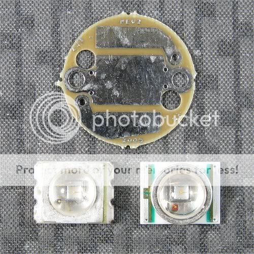
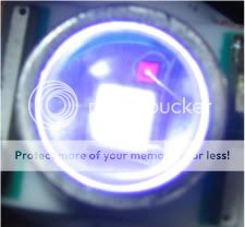
I put a Cree UV in my Surefire E1B and tried a McE2S 2-stage switch just for the heck of it. I know the light has a 2-stage driver so I figured it would just flicker like it did when I tried it before the mod. I noticed if I just barely made contact, I could get this TINY die to light up RED!!!

I've seen this in the Osram golden dragon (I THINK:thinking: )in maybe the RA lights?? I'm not sure...memory sucks.:tinfoil:

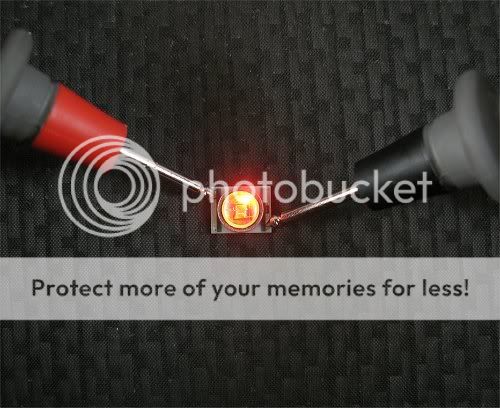
Anyway, I was wondering what it is, and if there is a specific current I can give the LED to light just the RED die continuosly. I can see when the UV comes ON the RED die goes OFF..:candle: It will turn on with the UV part for a split second and then goes off, but the UV stays lit. I have been able to have the red only light up when tapped just right.

Also would this hurt the LED??

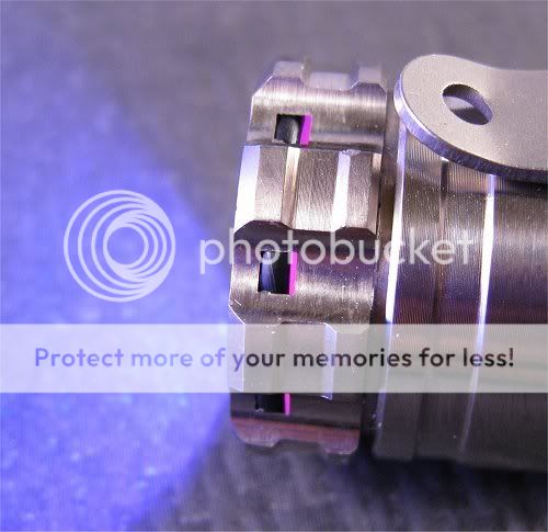
I can't get it to light constantly, but was able to get a crappy pic of what it is doing. I had to tap the side of the light while the timer on the camera helped get the shot.

It certainly looks cool!!:cool:
Anyone know whats up with this??:popcorn::popcorn::popcorn:

010-7.jpg


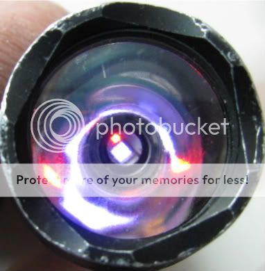
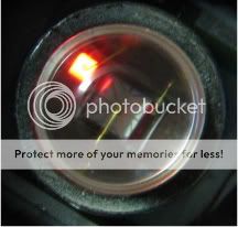
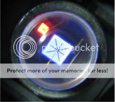
EDIT: Heres some better shots I was able to get.:thumbsup:

RED & UV
011-8.jpg
013-13.jpg
020-8.jpg
 
Last edited:

LukeA

Flashlight Enthusiast
Joined
Jun 3, 2007
Messages
4,399
Location
near Pittsburgh
reverse polarity protection.

If it was reverse polarity protection (like the GD), then it would never be on at the same time as the main junction.

My guess is that it's a diode for testing polarity. Maybe it goes "If you apply 1.5V to the LED, if it's connected right you will see a small red junction light up." That might prevent eye damage to an inspector. Just a guess.

I wish the white Crees had this/I wish there were more GD lights or boards that took advantage of that LED's secondary red junction.
 

DaFABRICATA

Flashlight Enthusiast
Joined
Jan 10, 2007
Messages
3,946
Location
Michigan
If you connect the Led in wrong polarity the current go to the red Led, that prevent blow the Led...


So is this FACT or just a guess that it is for reverse polariy protection?

If indeed it is RPP, then I'd like to know how this is even possible considering there is no way the battery is reversed..:shrug:...:popcorn:

I've tried searching for info and haven't found any:ohgeez:
 

DonShock

Flashlight Enthusiast
Joined
Dec 28, 2005
Messages
1,641
Location
Belton Texas
....If indeed it is RPP, then I'd like to know how this is even possible considering there is no way the battery is reversed......
If it is for RPP, and given that it's appearance is so intermittent and dim, it is probably just due to very small differnces in the electrical potential forming a path for a small amount of current to flow. The way you describe both coming on initially, then just the red, which then goes off once the UV coes on fully; that sounds like some small votage differences are appearing at unexpected points in the circuit connections at low currents.
 

Kiessling

Flashaholic
Joined
Nov 26, 2002
Messages
16,140
Location
Old World
I'd say LukeA has offered the best guess so far. And I am really jealous of your new avatar, Mr. DaFAB :D
Way cool.
 

DaFABRICATA

Flashlight Enthusiast
Joined
Jan 10, 2007
Messages
3,946
Location
Michigan
I'd say LukeA has offered the best guess so far. And I am really jealous of your new avatar, Mr. DaFAB :D
Way cool.


Thank you!

The minute I edited the pic and saw the results, I knew it was the one! :cool:
BTW...the new light came and I love it!!.. Thanks again:wave:


OT,
I hope there is a way to make the RED part stay lit separately.
I might have to contact Milkyspit and see if he can figure this one out..:thumbsup:
 

2xTrinity

Flashlight Enthusiast
Joined
Dec 10, 2006
Messages
2,386
Location
California
If it is for RPP, and given that it's appearance is so intermittent and dim, it is probably just due to very small differnces in the electrical potential forming a path for a small amount of current to flow. The way you describe both coming on initially, then just the red, which then goes off once the UV coes on fully; that sounds like some small votage differences are appearing at unexpected points in the circuit connections at low currents.
It would make little sense to use a red LED as reverse polarity protection, as opposed to a plain diode (which would be capable of absorbing a lot more reverse current than an LED without damage).

If the red LED were wired anti-parallel with the UV LED (eg, for reverse protection), it would need a voltage of about -2 at the terminals to even light up at all (there is a physical reason for this -- it takes 1.9 electron-volts of energy to generate a photon at 650nm). The UV LED should start to be visible at positive 3V and up. Unless your driver has output voltage swings of +-5V across the terminals, there is no way these would EVER be on simultaneously, unless the diodes have the same polarity. For that matter he way most LED drivers are wired, the negative output is connected to the most negative portion of the battery, so they can't produce a negative voltage at the terminals at all.

Anyway, there is certainly more to the story than just two LEDs being in parallel with each other. If that were true, the red LED would cotninue to get brighter and brighter as voltage increased, and it would actually burn out long before the turn-on voltage of the main diode was even reached. A large value resistor in series with the red diode would behave however similar to what you are seeing -- on but very DIM as long as the applied voltage is less than the minimum turn-on voltage of the UV LED.

A true constant-voltage, or constant-current driver (as opposed to PWM driver, or a flaky intermittent-contacting switch as in your case...) delivering a voltage lesss than the turn on voltage of the UV LEd (eg, around 2.5V applied) should be able to bias this LED so that the red diode only stays on. But there will be no way to make it very bright if there is ineed a hard-wired resistor inside the package.

Are you sure that the red LED goes OFF when the UV LED comes on, or is the red simply always so weak that the UV, once on at all, simply overpowers it? Have you tried looking at the emitter through a strong near-uv blocking filter to see if the red is still on?
 
Last edited:

Oznog

Enlightened
Joined
Dec 2, 2006
Messages
595
Man... weird!!!

I know red and blue combine to make violet-color, but not actually an ultraviolet wavelength... so I don't see why Cree would do that for a "violet" effect. And if the red turns off before the blue turns on then that's not even happening anyways.

I don't see anything in the Cree XLamp7090UVV-1.pdf datasheet suggesting anything like this.

I have a theory that somehow the red photons are needed to kick-start the UV diode, though I don't know of any such effect. It also seems odd since the red is not pointed at the UV emitter, but then it sounds mechanically impractical to place it anywhere else while manufacturing.

Or... maybe there could be a condition where the UV junction fails to conduct immediately, and the unloaded voltage rises above a forward-bias breakdown point, and that's acting like a clamping diode. In fact, that seem very consistent with your observations, right? The red turns on and then turns off when the UV turns on. That sounds like the die didn't conduct at first, the red conducted some, then the UV conducted and brought the voltage back down, turning off the red. So effectively the UV die may have an inherent LATCHING property, where it needs higher voltage to turn on but that it stays in a latched on-state when the voltage is brought back down.

Again... I have no idea why this would be, that's not a property of any diode I've ever heard of. Just... weird! Obviously it's there for a good reason. And it kinda looks like a lot of extra expense to add this feature, so whatever it does it must have been something important.
 

Ny0ng1

Enlightened
Joined
Oct 14, 2004
Messages
337
Location
Singapore
perhaps it a safety feature just to show that the led is running since it is a high power UV source. Similar with some infrared light which is more dangerous as it is invisible to the human eye.
just guessing
 

Oznog

Enlightened
Joined
Dec 2, 2006
Messages
595
Good theory, but I don't see how it could be for eye protection since it turns off when the UV die kicks in, and UV in this wavelength is still fairly visible anyways.

One other thing. OK, I'm on the theory that indeed these dies are in parallel and the UV LED must be exhibiting the latching property previously mentioned. If so, how is it possible that they could be in parallel when the Vf of red is about 0.5v less than the Vf of UV? The red should have stayed on and stolen all the current, unless they have a modified red die that has a Vf higher than the Vf of the UV. Any way you could measure the voltages in these different pics? I'd be interested at what voltage it turned off the red and turned on the UV, and whether the voltage drops when that happens under a current-limited supply.

It's just such a weird question- why you piggyback a red die inside a UV?? There's gotta be something interesting in the reason for it. Unless it's something really lame like a bizarre way to circumvent someone's patent.

Where'd you get the Cree UV, anyways?
 

Oznog

Enlightened
Joined
Dec 2, 2006
Messages
595
Img_6226.jpg


Well, the RPP theory might still be possible IF the red were only lighting because of some idiosyncrasy in the driver that delivered a low reverse voltage if the main LED was not conducting current.

I got this pic off an earlier thread. Hmm, the dies' bottoms are connected to the same piece of metal. The UV die has 2 bond wires but not the red... the red must be using the metal bottom as cathode I guess? The 7090 has an electrically isolated base though. That internal metal bottom can't be electrically connected to the external thermal pad, could it? The XR7090 UVV spec sheet mentions no restrictions on what voltage can be on that pad versus the anode.

Whatever the reason, it's damn odd that the spec sheet would not mention this at all. It affects the optical and electrical performance in some trivial ways but the spec sheet should still mention it.
 

darkzero

Flashaholic* ,
Joined
Oct 7, 2003
Messages
4,459
Location
SoCal
I don't understand how you got both the UV die & the red diode to light up simultaneously. The red diode is for reverse polarity like the GDs. IsaacHayes pointed it out so I went & confirmed it.

I have a few of these XR UV Crees. After reading your results I tested them all. I can only get the red diode to light up when powering up with reverse polarity. I can't get any of mine to light up simultaneously as you did in your pics. :thinking:

No matter how I power it up I only see the UV die light up & never the red diode before. Since you mentioned 2-stage, I have one in my PD mule & kept flashing low to see if I could get the red diode to light up... nothing. I guess it just may be the the driver in your E1B? I know it's not good but I want mine to light up like yours! :grin2:


Img_7335.jpg


Img_7331.jpg


(Sorry, just an excuse to post these. :whistle:)
Img_6799.jpg


Img_6809.jpg
 
Last edited:
Top