• You must be a Supporting Member to participate in the Candle Power Forums Marketplace.

    You can become a Supporting Member.

Sold/Expired Discussion - Programmable Hotwire Regulated Driver drop-in for D-M@g

Alan B

Flashlight Enthusiast
Joined
Nov 19, 2007
Messages
1,963
Location
San Francisco Bay Area
DSC_1066.JPG


Drop-in PHD-MD Regulator (Programmable Hotwire Driver for Maglite
(tm) D)

This drop-in upgrade for the popular Maglite(tm) provides significantly improved performance and versatility to the flashlight. It is compatible with a wide range of battery and bulb combinations and provides many new features including intensity control (dimming and regulation), battery overdischarge management and direct access to four light levels - high, low, middle and memory. The PHD-MD replaces the flashlight's plastic power switch assembly with the above pictured 6061 T6 aluminum "Sled" containing two circuit boards. A wide range of bipin bulbs generally in the 6 to 24 volt range is plugged into the ceramic socket. A suitable battery pack with a voltage equal to or higher than the bulb is installed, and the reflector and lens upgraded to handle the increased temperatures. Common bulbs are in the 30 up to 250 watt range.

One favorite example is the so called Mag85. A 30 watt Welch Allyn WA1185 bulb is used and the battery pack can be nine AA rechargeable nickel metal cells in a battery holder that drops right into a 3D Maglite. With this bulb the range of available output is from a few lumens to about 1500 bulb lumens. This range is approximately from the output of one candle up to a car headlight.

The Feeler thread is closed (but contains a wealth of useful information), and the Discussion, User Manual, and FAQ have been separated and moved out of the Feeler thread. The Ordering/Sales thread has been started as well (see link below). New interest posts and orders should go in the Ordering thread. There are also design threads and programming threads, so there is a wealth of information available.

This thread is for questions, suggestions and discussion about the Programmable Hotwire Regulated Driver drop-in for the D-M@g. The User Manual and FAQ will live in the first few posts here until they are mature and then they will move to a permanent website.

Thanks for your patience and support.

Thread Table of Contents

1. Introduction (This Posting)
2. Frequently Asked Questions
3. User Manual
4. Semi-Kit Assembly Notes
5. reserved
6. Discussion thread begins


Related Threads

Review by LuxLuthor:
http://www.candlepowerforums.com/vb/...d.php?t=230519

Orders & Sales Thread:
https://www.candlepowerforums.com/threads/231886

Feeler Thread:
http://www.candlepowerforums.com/vb/...d.php?t=218506

Advanced - Programming the Regulator:
https://www.candlepowerforums.com/threads/231685

Design Collaboration Part I:
http://www.candlepowerforums.com/vb/...d.php?t=186291

Design Collaboration Part II:
http://www.candlepowerforums.com/vb/...d.php?t=209098

Design Collaboration Part III:
http://www.candlepowerforums.com/vb/...d.php?t=220475

Maglite is a trademark of Mag Instruments, who make the nice aluminum flashlight that this Regulator fits into.
 
Last edited:

Alan B

Flashlight Enthusiast
Joined
Nov 19, 2007
Messages
1,963
Location
San Francisco Bay Area
Programmable Hotwire Driver FAQ

This FAQ covers the M@gSled Hotwire Driver. Much of what is here applies also to JimmyM's and wquiles' variant, but there are some differences.

What is a Hotwire?

The term Hotwire is generally applied to high power incandescent flashlights, especially ones where the bulb is being overdriven to achieve higher output and efficiency.

What is a Programmable Hotwire Driver?

This is a tiny programmable computer chip controlling a large power transistor (FET) switch that sits between the battery and the bulb. By controlling the switch with PWM (pulse width modulation) it can control the temperature of the filament and the light output of the bulb. This can be used to provide many useful features including voltage regulation, soft start, intensity control and battery protection.

What does it do for my Incandescent Flashlight?

The regulator provides soft-start for the filament to limit inrush current and extend the life of the bulb. It provides regulated voltage levels to make the output level constant regardless of battery condition, and to allow lower levels of output when desired. Lower levels of output make the batteries last longer and reduce heat, making the light far more useful than "maximum only". Using more cells in the battery pack provides more energy and longer runtime. The regulator also monitors battery condition and can shut down before overdischarging the battery. This can allow use of unprotected cells that can deliver higher current. It also monitors temperature inside the flashlight and can shut down the light when high temperatures are reached. The adjustable ceramic bipin bulb socket supports many different available bulbs.

What is the User Interface like?

Since the regulator is programmable the user interface can be changed, and there will be many versions. The software allows the user to tailor the interface to their needs. Just to give a flavor of my own current favorite UI:

click from off to memory level
click from on to off
press from off to lowest level
press while on to ramp the memory level, alternating direction with each press
double click anytime to maximum level
triple click to middle level


What are the Configurable Parameters?

examples of parameters that can be changed by programming the regulator (the following list is not complete):

maximum bulb voltage
minimum bulb voltage
battery chemistry
number of cells
number of clicks to enable/disable lock out
temperature of overtemperature shutdown

See the Programming Thread for more information on this

What is the Lockout feature?

It effectively locks the flashlight off until the unlock sequence is entered.

What are the Voltage and Current Ratings?

Presently estimate 34V battery and 12A bulb current as the maximum rating (subject to change). Some testing has been done but more experience will guide the final rating determination. Absolute Maximum ratings are 40V Peak battery voltage and 15A RMS bulb current. The closer the unit is operated to the maximum values the more likely it will blow the fuse or damage a component. The fuse is 15A, the FET is rated much higher.

What is the relationship between Battery voltage and Bulb voltage?

The battery voltage should be greater than the desired bulb voltage. This regulator cannot increase voltage, it can only reduce it. The ideal situation is when the loaded battery voltage is just higher than bulb voltage. When the battery voltage is twice the bulb voltage the duty cycle will be only 25%, and the peak current and voltage will be twice the bulb rating. The small duty cycle means that change steps in the PWM are larger, as one count is a larger proportion of a smaller duty cycle. For best performance select a battery/bulb combination where the battery voltage under load is about 10 to 30 percent higher in voltage than the bulb. It is not recommended to use battery voltages more than twice the bulb voltage (though it will work).

When will it be Available?

The M@gSled(tm) is shipping starting August.

What will the Regulator Cost?

Prices start under $100. There are a lot of parts some of which are custom and expensive such as the aluminum sled. The parts count (mechanical and electrical) is over 40 in this regulator. (The prices are stated in the Order thread).

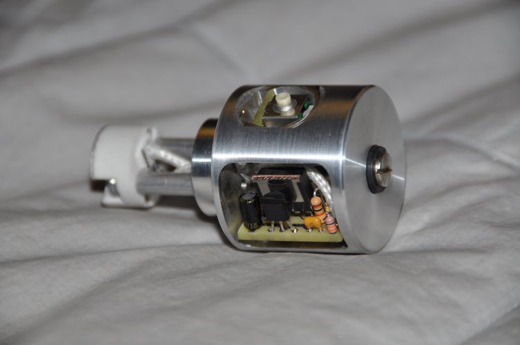
How large is the Regulator?

The M@gSled regulator is designed to occupy the same space as the stock switch in a D size Maglite (Maglite is trademarked by Mag Instruments)(We have no affiliation to Mag Instruments, other than using their excellent aluminum flashlight parts to house our switch). It rests against the stop ring in the front, the same as the stock switch. The positive battery terminal sticks out more than the stock switch allowing flat terminal batteries to work properly. The position of the positive terminal places the battery stack approximately 4-5mm further toward the tailcap than a stock M@g, so the spring will need to have enough compliance and space to handle this. This is not a problem in most configurations as there is a lot of room in a stock spring, but some special situations may not have enough room without extending the tailcap.

How is the Regulator installed?

Remove tailcap and batteries. Remove head/reflector/lens assembly. Pry the switch rubber cover out. Using a 3/32 (or size as required) hex wrench through the center of the switch turn counterclockwise and loosen the switch. Push the switch in to the "on" position and slide the switch and bulb assembly out the tail end of the body tube. Remove the pushbutton swtich board from the PHD Sled using needlenose pliers or a loop of wire. Slide the Sled into the body tube against the stop ring. Align the sled with the switch hole. Tighten the lockscrew through the hole in the pc board with the hex wrench. Plug in the switch. Install and clean the bulb. Replace the lens and reflector with high temperature capable units (depending on the bulb power). Install the head assembly. Install battery pack. Test.

Does this retain the focussing capability of the M@g?

The focus is adjustable but the fast cam is removed. Coarse adjustments are made by changing the height of the bipin bulb socket using spacers. Fine adjustments are made by turning the head of the light.

What is the Resistance of this Regulator (or How many MilliOhms is it)?

MilliOhms refers to the resistance to current flowing through the regulator. The FET switch is about 5. The fuse is about 5. Not sure yet what the rest is, but it is designed to be very low. The socket probably has more resistance than the regulator. More here later.

What Bipin Bulb Socket is Used?

CPF Member Kiu will not sell us his bipin sockets. A baseline socket will be provided, with the option of the user providing a socket such as a Kiu. Osram sockets will be available as an option.

Does the Regulator get Hot?

The regulator switch is "on" or "off", and does not dissipate much power. It should not get hot. During extended tests it did not get hot, or even warm. The bulb will likely heat the regulator more than the current.

Does the Regulator Shut Down when Overheated?

The default programming configuration uses the cpu's internal temperature sensor to shut the regulator down at approximately 60C to protect both the regulator and the batteries. This value can be changed.

What is PWM?

PWM stands for Pulse Width Modulation. The energy delivered to the bulb is controlled by turning it on and off quickly. Adjusting the duty cycle (percentage of time on) controls the bulb power. The regulator does this about 250 times per second.

What Voltage and Current go to the Bulb?

The switch is very low resistance, when it is "on" the full battery voltage is delivered to the bulb, and the current is determined by the filament resistance. The RMS value of the voltage and current are correct for the bulb's DC values. However the peak voltage and current are higher. The PWM duty cycle controls the power in the filament and delivers the correct RMS values.

What happens when battery voltage is below the desired bulb voltage?

The PWM goes to 100 percent duty cycle (fully on) and the driver becomes direct drive (and is no longer regulating). It still provides soft starting, and if the ramping is used to dim the bulb it may go back into regulation at a lower voltage.

What happens when the battery voltage gets too low?

This depends on the programming in the regulator, but it must reduce the load or go off to protect the battery. The current software in the M@gSled blinks off for 200 milliseconds and then comes back on at half bulb voltage if the battery will support that. If the battery still won't stay above the safe voltage it repeats the cycle, dropping to a lower voltage until either the battery will support the load or the filament voltage drops below minimum and the regulator turns off.

How much power does the Regulator consume?

When the light is on the power consumed by the regulator is approximately 7 mA. When the light is off the power consumed is approximately 300 uA. A 2000 mAH battery pack (such as an AA Eneloops) would take about 270 days to run down at this rate. Loosening the tailcap to lockout the light may reduce or eliminate this leakage current. Note that this current changes with voltage and further changes to these values will occur as the design is finalized.

Does the light Flicker?

At this frequency the thermal inertia of the filament makes any flicker very small and it is not visible.

What is RMS voltage?

RMS stands for Root Mean Square, but that is just the engineering/math term for "effective" voltage. So if we have 10 volts RMS it will produce the same light from the bulb as 10 volts DC.

How can I measure RMS voltage?

Use an AC+DC RMS meter and read it directly, or use a regular average DC meter and make two readings, one of the battery voltage and one of the output average DC voltage. Multiply the battery voltage times the average DC voltage. Take the square root and the result is the RMS voltage. This calculation requires square waves to work properly, so it works best with a light load. Waveform distortion will make the results inaccurate.

My meter has RMS but the values don't agree?

Most RMS meters are AC RMS, not AC+DC RMS. AC RMS meters throw away the average DC part of the reading and cannot be used. Use the DC range and treat it as an average DC value as in the procedure above.

Does the Regulator make Noise?

The regulator is quiet. The pulses in the bulb may make a slightly audible noise, depending on the bulb filament. It is not loud and the noise is reduced at high output levels, increasing at lower voltage outputs (such as when the output is ramped to a low level). The noise level is also a function of the peak current (due to magnetic forces in the filament), so using higher voltage batteries increases the noise level.

Will there be a High Voltage model?

Probably. The parts in the standard models are rated to 40 volts ABSOLUTE MAXIMUM. This includes transients, etc, so we should not go above about 34 volts. There are higher voltage parts available, we need to test those at some point and see if there are any issues with them at higher voltages. They have ratings of about 60 volts MAXIMUM, so that should get us to about 12S or 50 volts. It is also possible for the parts to be changed. The FET, regulator and voltage scaling resistor for the ADC need to be changed to go to a higher voltage range. An application note could be developed to explain this in more detail for those who wish to experiment.

What are the Voltage Ranges?


The regulator has a number of voltage ranges (up to 6) it can operate in, somewhat like changing ranges on a multimeter. These ranges are selected by a combination of jumper and the software. If the jumper is installed the software can select the range that will handle 2, 4 and 8 series connected Li-Ion cells at 4.2 volts per cell. With the jumper out the ranges are 3, 6 and 12 Li-Ion cells at 4.2 volts per cell. NOTE that 12 cells require a special high voltage model of the regulator.

What does 2S, 4S or 8S Voltage Rating Mean?

Lithium Ion cells are generally 4.2V per cell (some are lower). The S rating is for series connected cells, so 4S is 4 cells in series for 4 times 4.2 volts or 16.8 volts. You may also see notations like 4S2P which means 4 cells in series and two stacks in parallel, for a total of 8 cells. Series cells raise the voltage, parallel cells raise the current capacity and ampere-hour ratings.

Will there be a model for the "C" M@glite?

I'm not planning it at this time. JimmyM may do one sometime in the future. It is a tight fit and compromises will likely be required.

Will there be a model for the Surefire M6?

wquiles is working on this.

What type of parts are used in this Regulator?

This regulator uses a mix of standard through-hole and surface mount parts. The early models were entirely through-hole parts. It is not hard to work on and might possibly even be offered as a kit at some point. The other variants from JimmyM and wquiles will most likely use entirely surface mount parts.

What is the difference between this Regulator and JimmyM's?

Jim's variant of this regulator is designed to fit under a KIU base. It is smaller and lower in cost. It will be more difficult to install and reprogram due to its location and the plastic M@g switch will remain. Jim is using a different variant of the CPU so it takes slightly different software, but both are Atmel AVR series chips (and use the same software and programming tools). It uses surface mount parts allowing it to be smaller.

What is the difference between this Regulator and wquile's?

Will's variant of this regulator is designed to fit into a special SF M6 battery pack.

What happens when a bulb blows?

This depends on exactly how the bulb blows. The regulator will not detect that it has happened. If the bulb manages to short and present a really low impedance to the regulator the current spike may blow the onboard fuse, but this is not likely. The FET switch is very robust and can handle large surge currents so it should be fine.

What happens if the fuse blows?

Be thankful that the fuse blew and not the battery pack. After the fuse blows the regulator will no longer get voltage from the battery as the fuse is the first thing in the circuit. It will have to be replaced. To keep it small and low resistance the fuse is soldered to the board. It looks like a green tubular resistor and is located right next to the positive terminal of the battery on the circuit board. Replace it with a 15 amp picofuse. Make sure that the problem that caused the fuse to blow is repaired before returning the unit to operation and double check that the battery positive terminal is not shorted to the sled after reassembly.

What happens if the battery polarity is reversed?

The transistor switch behaves as a high current capable diode when powered in the reverse direction. The battery will be connected to the bulb through this diode. Depending on the choice of battery voltage versus bulb voltage, the bulb may be very bright, or it may instaflash (blow out). The regulator itself is reverse polarity protected so it is not likely to be damaged. Some battery packs have charging jacks in the negative end that may short on the positive battery connector of the regulator, causing high currents, heating and damage to the batteries and battery pack.

What if the Regulator needs repair?

Depot repair will be worked out later. Schematics and software are available on the web for self-repair.

Questions about Programming

For questions about Programming the Regulator see the Programming FAQ:
https://www.candlepowerforums.com/posts/2953206&postcount=2


Links:

Design Collaboration Part I:
http://www.candlepowerforums.com/vb/...d.php?t=186291

Design Collaboration Part II:
http://www.candlepowerforums.com/vb/...d.php?t=209098

Design Collaboration Part III:
http://www.candlepowerforums.com/vb/...d.php?t=220475

Feeler Thread:
https://www.candlepowerforums.com/threads/218506

Review by LuxLuthor:
https://www.candlepowerforums.com/threads/230519

wquiles SF-M6 variant:
http://www.candlepowerforums.com/vb/...d.php?t=215806

JimmyM's D-M@g variant:
http://www.candlepowerforums.com/vb/...d.php?t=216160

Maglite is a trademark of Mag Instruments. This regulator is not produced by Mag Instruments - we have no relation to the company. We just like their aluminum housing. It is a great starting point.

Corrections, suggestions and questions to:
 
Last edited:

Alan B

Flashlight Enthusiast
Joined
Nov 19, 2007
Messages
1,963
Location
San Francisco Bay Area
User Manual to go here soon

Product Description

Compatibility

This regulator is designed to fit in the space the standard switch occupies. It has been tested and found to fit in many clone lights based on the D Maglite(tm).

Cautions

Installation

Adjusting the Socket Height

The regulator is supplied with hardware designed to place Welch Allyn bulbs such as the 1185 near the proper focal point for standard reflectors. Proper focus should be approximately one turn out on the head. For other bulbs and reflectors adjustment of socket position may be required.

The updated aluminum sled has both 4-40 SAE and M3-0.5 Metric threads. This is to allow use of either type of spacer for the socket. Take care to avoid cross-threading. Use only screws or standoffs with threads in good condition and test to determine which holes they fit properly into. When tightening the socket avoid placing too much compression on the ceramic as it is easy to crack.

Refer to the FAQ for details on installing the regulator sled. (they will be detailed here later)

Removing the Regulator from the Flashlight

Remove the rubber switch cover.
Remove the switch using needlenose pliers or a loop of wire.
Loosen the hex setscrew through the PC board.
Slide the regulator out toward the tailcap.

Operating


Programming

See the Advanced Programming Thread
https://www.candlepowerforums.com/threads/231685

Specifications

subject to change

40V maximum battery voltage
6V minimum battery voltage
13A maximum RMS bulb current

Service

Notes

Maglite is a trademark of Mag Instruments

eof
 
Last edited:

Alan B

Flashlight Enthusiast
Joined
Nov 19, 2007
Messages
1,963
Location
San Francisco Bay Area
Semi Kit Assembly Notes DRAFT 0.1

The sled assembly is mechanically tight, this kit is for advanced builders
Do not attempt this kit unless you can work in a tight space

A ball end hex wrench will be required for assembly
Soldering is required
Flush cutters are required for trimming leads close to the pc boards
Wire strippers, soldering pencil with fine tip and solder are required
Hemostats or needlenose pliers are required

Refer to photos for Assembly:
http://picasaweb.google.com/Alan.Bi...authkey=Gv1sRgCLuMvMSaod2y1QE&feat=directlink

Assemble the small switch board S2E:
Six pin socket mounts flat to board
- One lead of the socket will have to be cut as there is no room for pad
- Nomenclature S2E is on non-component solder side of board
Perpendicular pushbutton goes on component side of pcb
- Insure the pushbutton is perpendicular to the board
Solder on the non component side
Trim switch wires close to board

Assemble the long thin programmer board P2E:
Six pin socket goes on end, flat to board
- Nomenclature P2E is on non-component solder side
Note the square pads on the programming plug holes, this is pin #1
Using a red felt pen color the edge of the pcb adjacent to pin 1 to aid in installing the cable correctly
Insure the programmer six pin male plug goes into the correct two rows of holes toward the switch
- There should be one row of holes unused toward the six pin socket (away from switch)
It requires some force to seat this plug, the shorter pins go in the board
Solder on the bottom side
Trim switch wires close to board

Assemble the sled and regulator board:
Cut socket leads to 2.0", 2.6" and strip 1/8"
Thread through sled front hole and out left side (front hole facing you and pushbutton hole upward
Gently push socket down to sled, maximizing wire length for working
Align pcboard next to sled with battery terminal away from socket
Route socket wires to pcboard
Longer wire goes into hole adjacent to green fuse near battery terminal
Shorter wire goes into hole adjacent to FET (large transistor)
Insure all wire strands are in holes - avoid shorts
Solder 2 socket wires to pcboard
Trim socket leads below pcboard close to avoid shorts
Trim any other leads over 2-3mm below the pcboard
Slide board into the sled routing wires away from six pin plug
Flat fiber washer installs between sled and regulator board batt terminal
Shoulder washer installs from outside of sled, shoulder into the sled hole
#6 Philips screw through both fiber washers into battery terminal, center and screw in, leave slightly loose
#4 Install hex socket head screw through internal tooth lockwasher, regulator pcb, short spacer, into sled
- route wire up and away from screw during installation, avoid damaging wire insulation
- Tighten both screws carefully, snug down but do not overtighten
Check for shorts visually below pcb to sled
Route wires to clear the six pin plug, avoid bending component leads
Attach socket loosely to sled with screws, split lockwashers, through socket and spacers or standoffs
Two screw holes are 4-40 SAE, two are M3? Metric, take care to use proper holes
Caution - ceramic is easy to crack
Very carefully tighten socket screws only finger tight enough to just flatten split washers
Using a meter check for short between battery terminal and sled
Visually inspect carefully looking for shorts, loose bits of wire or metal, etc

Program and calibrate - see separate instructions in the programming thread
-Jumper in for 2S/4S/8S or out for 3S/6S/12S voltage range

Install - see separate instructions in the user manual in the discussion thread
 
Last edited:

Alan B

Flashlight Enthusiast
Joined
Nov 19, 2007
Messages
1,963
Location
San Francisco Bay Area
Status Update:

First Article Regulator arrived in good shape from LuxLuthor. Plan to change the resistor and recalibrate then test for sufficient input voltage range.

SMT Prototype PC boards are in the mail (actually UPS). So they are on the way.

The raw metal was due today (I didn't verify that it arrived at the machineshop).

Microscope arrived and seems to work.

New thread started today for Programming this Regulator.

* Need to identify the Metric thread used for the Kiu standoffs.

* Need to clear up the workbench where the SMT rework station and microscope are going to sit.
 

Alan B

Flashlight Enthusiast
Joined
Nov 19, 2007
Messages
1,963
Location
San Francisco Bay Area
I've been busy with other high priority projects this weekend, but I did take a few minutes and make A123 M1 sleeves by boring out schedule 40 PVC pipe. I cut them 2.5" long and bored them out to 1.070". The number six sleeve was cut shorter to fit in front of the tailcap, down to about 1.7" long.

To my surprise, with the tailcap spring removed, SIX A123M1 LiFePO4 Cells JUST FIT with the stock M@g switch and the tailcap installed. We'll have to see, it probably won't fit with my slightly longer regulator sled installed, but it will be very close.

When I tested before the cells were off center lying in the bottom of the tube and so they didn't sit in the normal position. This pushed them back a bit further.

Too bad it is so difficult to shorten the sled a bit. Perhaps someday I can do that, but it is not a small project.
 

Alan B

Flashlight Enthusiast
Joined
Nov 19, 2007
Messages
1,963
Location
San Francisco Bay Area
I measured a metric bulb standoff. They appear to be M3 threads at 0.500 mm pitch. Anyone else care to verify that? Is that what folks want??
 

Alan B

Flashlight Enthusiast
Joined
Nov 19, 2007
Messages
1,963
Location
San Francisco Bay Area
SMT PCB prototype arrived today. It will be a few days before I can build and test one, but this is next. Then it will go to LuxLuthor for evaluation.
 

JimmyM

Flashlight Enthusiast
Joined
Aug 30, 2006
Messages
2,852
Location
Boston, MA, USA
SMT PCB prototype arrived today. It will be a few days before I can build and test one, but this is next. Then it will go to LuxLuthor for evaluation.
I'm interested to see the differences between hot-air reflowed boards and the oven reflowed baords.
What solder paste are you using? I forget of you mentioned it.
 

Alan B

Flashlight Enthusiast
Joined
Nov 19, 2007
Messages
1,963
Location
San Francisco Bay Area
Me too.

I need to find out the details about the paste I have. A guy on the internet supplies it to Amateur Radio and other hobbyist projects, it is available in small quantities inexpensively. I'll probably use something else later, but have that to start with. I suspect it is no-cleanup required but don't really recall. The guy has a website with techniques for doing low cost SMD work with minimal equipment, such as embossing pencils for hot air and mug warmers.

How did you choose the paste you are using?

At work we had serious problems with water-clean paste, but those boards were very sensitive analog boards. These boards should be pretty insensitive. Apparently the water wash pastes are pretty acidic and some sneaks under the parts and never comes out and attracts moisture causing some current leakage. The no-wash or solvent-wash flux doesn't attract water. This info is a few years old and may not be accurate anymore.
 

JimmyM

Flashlight Enthusiast
Joined
Aug 30, 2006
Messages
2,852
Location
Boston, MA, USA
Me too.

I need to find out the details about the paste I have. A guy on the internet supplies it to Amateur Radio and other hobbyist projects, it is available in small quantities inexpensively. I'll probably use something else later, but have that to start with. I suspect it is no-cleanup required but don't really recall. The guy has a website with techniques for doing low cost SMD work with minimal equipment, such as embossing pencils for hot air and mug warmers.

How did you choose the paste you are using?

At work we had serious problems with water-clean paste, but those boards were very sensitive analog boards. These boards should be pretty insensitive. Apparently the water wash pastes are pretty acidic and some sneaks under the parts and never comes out and attracts moisture causing some current leakage. The no-wash or solvent-wash flux doesn't attract water. This info is a few years old and may not be accurate anymore.
I've read that the no-clean paste can cause problems with high impedance boards. I was concerned with that because of the Vbat, Vbulb, and Vlow resistor values I use. So I figured that if I had to wash the baords anyway, I might as well use paste that is intended to be washed with water.

To clean my boards I perform 3 steps.
1) Immerse in shallow HOT water (my tap water is ~160F) for a minute or 2.
2) lightly scrub the baords with a soft toothbrush
3) run hot water over the baord for another minute.

Let me know how it goes. I've reflowed some components with a different paste during testing with the hot air pencil. I had issies with bridging and tombstoning, but that was before I understood what "as little paste as possible" meant. With hand application of paste by swab or syringe I ended up with lots of stray solder beads/balls. With water based flux, cleanup would have been a non-issue.
 

LuxLuthor

Flashaholic
Joined
Nov 5, 2005
Messages
10,654
Location
MS
Alan, here is a shot I took of the bulb sizes, vis-a-vis socket stem length. I tried to line up the bulbs based on the bottom of their envelope. I also got my 5W resistors so I can finish testing Jimmy's. Big difference in sizes.

 
Last edited:

Alan B

Flashlight Enthusiast
Joined
Nov 19, 2007
Messages
1,963
Location
San Francisco Bay Area
I've read that the no-clean paste can cause problems with high impedance boards. I was concerned with that because of the Vbat, Vbulb, and Vlow resistor values I use. So I figured that if I had to wash the baords anyway, I might as well use paste that is intended to be washed with water.

To clean my boards I perform 3 steps.
1) Immerse in shallow HOT water (my tap water is ~160F) for a minute or 2.
2) lightly scrub the baords with a soft toothbrush
3) run hot water over the baord for another minute.

Let me know how it goes. I've reflowed some components with a different paste during testing with the hot air pencil. I had issies with bridging and tombstoning, but that was before I understood what "as little paste as possible" meant. With hand application of paste by swab or syringe I ended up with lots of stray solder beads/balls. With water based flux, cleanup would have been a non-issue.

As is often true, generalizations are only right part of the time. The water wash flux must be water soluble and they often use some type of acid, so they are more prone to absorbing water and becoming conductive. Washing them off is important. They can be conductive and even corrosive if not washed off. The actual characteristics will vary with the actual chemistry, so generalizing like this is dangerous.

The no washup flux is generally rosin based, and so is water repellent. It can be washed up with solvents such as alcohol. If not washed off it is designed to have high impedance and not be corrosive.

If you wash off water based flux, and a little remains, it can be a problem. If you wash off rosin flux and some remains it is likely a lesser problem. Problem is that some flux tends to remain under the flat components, between the pcb and the resistors, capacitors, etc that sit down tight. It is difficult to get it out as surface tension prevents flow and brushes cannot reach under there.

Fab houses hate solvent washup, so they don't like washing up no-wash flux.

The sensitivity of the circuit is very important here. These circuits are NOT very high impedance sensitive, so we can probably do anything and it will work fine. The systems we had trouble with were sensitive to parts per million and had megohms of impedance, so they were significantly more susceptible.

For these most demanding boards the best system was no-wash flux that was then solvent washed. That is supposed to be best. The second place position is harder to call - between no-wash flux that is not washed, and water-wash flux that was properly water washed. Either of those should be fine for most circuits. The worst is clearly the water washed flux that was not washed. We had one vendor give us that on some moderately sensitive boards. They worked fine for awhile and then started drifting and corroding. Definitely avoid that.

I forgot to ask, which solder alloy have you settled on?
 
Last edited:

Alan B

Flashlight Enthusiast
Joined
Nov 19, 2007
Messages
1,963
Location
San Francisco Bay Area
The new boards arrived, and they look good. This weekend I plan to build one or more up and test. Then I'll ship one to LuxLuthor for more beta testing.

I need to get the AC power wiring set up on my new work area for the board preheater and hot air rework station, and clear it further for room to actually work.

There is a CPF gathering in San Jose on the 30th. Hopefully I'll have a couple of regulators to show there. Maybe even have my 6D M@g working. And be able to test one in one of Johnathan's 15K Elephant M@gs.
 

cnjl3

Enlightened
Joined
Jan 22, 2006
Messages
723
Location
Deep in the heart of Texas
I have a question, I have already made my selection for my regulator which I chose the Phillips 5761 @ 7.2V and it eats 5.5amps per LuxLuther's charts. Now with a regular regulator (that sounds funny!) to estimate runtime you normally just divide the AH of your battery pack by the A of your lamp and you get a rough runtime figure. Since PWM allows you to add an additional cell to the battery pack - how do you figure your additional runtime with the extra cell since technically the extra cell is still in series and usually amperage doesn't add up like in a parallel battery scenario? I see that you mention how to select your battery voltage - but I don't see much about amperage consumption.

What is the relationship between Battery voltage and Bulb voltage?

The battery voltage should be greater than the desired bulb voltage. This regulator cannot increase voltage, it can only reduce it. The ideal situation is when the loaded battery voltage is just higher than bulb voltage. When the battery voltage is twice the bulb voltage the duty cycle will be only 25%, and the peak current and voltage will be twice the bulb rating. The small duty cycle means that change steps in the PWM are larger, as one count is a larger proportion of a smaller duty cycle. For best performance select a battery/bulb combination where the battery voltage under load is about 10 to 30 percent higher in voltage than the bulb. It is not recommended to use battery voltages more than twice the bulb voltage (though it will work).

You lost me with your explanations of how to measure current - but I am quite content knowing that I can measure within .05V of what JimmyM set my JM-PHD-D1-Hotwire regulator that I feel that I really dont need to bother with amperage readings. Is my current euphoria going to get me into trouble?

The same formula would work if you could measure peak current, but that is not as simple as measuring peak voltage.

You could use a scope and measure peak current and duty cycle and calculate from that.

I believe you can also measure peak voltage, average voltage and average current and calculate RMS current from those.


I did this quickly and hopefully correctly:

rmsCurrent = squareRoot ( meanCurrent * meanCurrent * batteryVoltage / meanVoltage )

You can measure meanCurrent, meanVoltage and batteryVoltage with a regular averaging meter. (Mean is the average).

This is valid only for a clean square wave going from zero to batteryVoltage. Waveform distortion such as a battery under heavy load will cause some inaccuracy.
 

Alan B

Flashlight Enthusiast
Joined
Nov 19, 2007
Messages
1,963
Location
San Francisco Bay Area
I have a question, I have already made my selection for my regulator which I chose the Phillips 5761 @ 7.2V and it eats 5.5amps per LuxLuther's charts. Now with a regular regulator (that sounds funny!) to estimate runtime you normally just divide the AH of your battery pack by the A of your lamp and you get a rough runtime figure. Since PWM allows you to add an additional cell to the battery pack - how do you figure your additional runtime with the extra cell since technically the extra cell is still in series and usually amperage doesn't add up like in a parallel battery scenario? I see that you mention how to select your battery voltage - but I don't see much about amperage consumption.

You lost me with your explanations of how to measure current - but I am quite content knowing that I can measure within .05V of what JimmyM set my JM-PHD-D1-Hotwire regulator that I feel that I really dont need to bother with amperage readings. Is my current euphoria going to get me into trouble?

If you measure average current, average bulb voltage and full battery voltage the equation will give you RMS current.

The simple way to estimate runtime here is to use watt-hours. For the battery multiply amp hours times nominal voltage to get watt hours. Divide by the bulb's power consumption in watts (from amps times volts). That gives hours.

2.3AH * 3.3V * 6 cells = 45.5 watt-hours

If you run a bulb at 160 watts then

45.5 / 160 = 0.28 hours or about 17 minutes.
 
Top