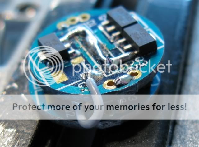
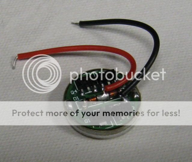
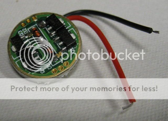
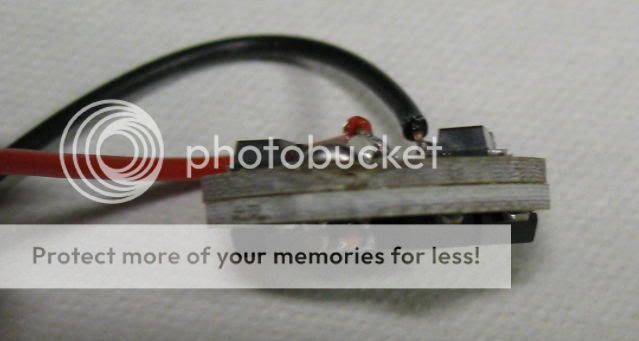
Just checking to see if anyone has had issues with DX 1400mAH drivers? I've heard that the solder job on most of them is poor...but has anyone ran into them not running at 1400mAH?
Are they finally shipping them also? Or do they just say they will be shipping 5-10days? I remember them being on backorder for 3-4months....
What is the input voltage for the 1400mAH?
I'm wanting to make a 2 mode MC-E w/2 1400mAH...is that going to work for the MC-E's?
Are they finally shipping them also? Or do they just say they will be shipping 5-10days? I remember them being on backorder for 3-4months....
What is the input voltage for the 1400mAH?
I'm wanting to make a 2 mode MC-E w/2 1400mAH...is that going to work for the MC-E's?