My first sandwich driver

old4570

Flashlight Enthusiast
Joined
Feb 15, 2009
Messages
2,902
Location
Melbourne - Australia
Eeeer I think it works ...


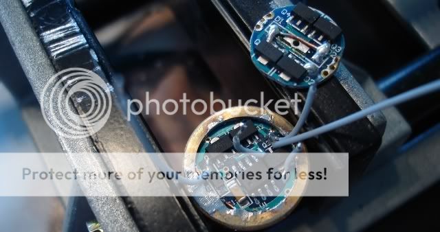
Back to back : AMC 7135 1400mAh and a 2 mode 1000mAh driver I had lying around ..

So far I seem to have two modes under low voltage testing , as seen it has a Q5 hooked up to it for testing ..
Time to ramp up the battery power to a CR123A and see if I still have 2 modes ...
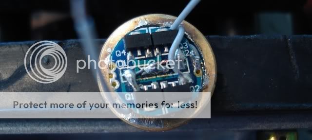
Ok = Update ...

No multi mode , but it does run ok ... 1.25A before the driver , 1.19A to the led ...

I sure would have liked multi mode , I have 2 5 mode drivers on order , so hooking things up should be easier ..
Oh well .. I did try to run power through the middle or the + terminals/pads on the boards where the springs go , possibly a mistake ..
Maybe not ? Anyway , I did it my way , and probably wont see more than 1400mAh for my effort .
Its late , time for bed
 
Last edited:

jar3ds

Flashlight Enthusiast
Joined
Sep 12, 2005
Messages
1,988
Location
USA
nice! thanks for sharing.. let us know how it goes...

what crap did you use to bond them together?
 

Justin Case

Flashlight Enthusiast
Joined
Mar 19, 2008
Messages
3,797
Is this for one of your Solarforce mods? If so, how do you plan to connect Batt+ to the driver, since your sandwich has the component sides facing out?

What was the 1000mA 2-mode board and how did you wire the two together?
 
Last edited:

tx101

Flashlight Enthusiast
Joined
May 17, 2008
Messages
2,357
Location
London UK
More like this

Maybe you should check your soldering ?
I have just build a similar sandwich for a P7 build
and it works as it is suppose to
 

Justin Case

Flashlight Enthusiast
Joined
Mar 19, 2008
Messages
3,797
Yes, I know all about the download and netkidz wiring diagrams. But that is how they wire up AMC sandwiches. The question is how old4570 wired his sandwich.
 

old4570

Flashlight Enthusiast
Joined
Feb 15, 2009
Messages
2,902
Location
Melbourne - Australia


I followed this one ...

But did face to face , joined by soldering ... [ Yes tricky ]

Next one I do I will isolate the basses , then glue them together ...

Batt contact = just solder in a contact spring ...

Problem is , all these are for mag mods ..

I need a compact driver for P60 pill ,so they need to be back to back ..

Its all about learning , at least it seems to be an efficient single mode driver .
I have 2 more 1A 5 mode drivers , + I ordered the ones from DX everyones seems to use [ 5 mode ] ...

But what ever I use , needs to be compact , as there is only about 6.5mm of space for the driver ...

... Like I said , I think I stuffed it up for multi mode ...
 

Justin Case

Flashlight Enthusiast
Joined
Mar 19, 2008
Messages
3,797
That connection diagram/photo is definitely right. How are you powering your sandwich? Power sent to the multimode or to the slave?
 

old4570

Flashlight Enthusiast
Joined
Feb 15, 2009
Messages
2,902
Location
Melbourne - Australia
Power comes from the 1400mAh Single mode ..

I think the problem is , Im feeding power through the + pad ..
Its also regulated as it goes in by the slave driver .. .. + Then I also have the jumper wire for + Power .

So two sources of + power ..

I will try again , this time isolating the basses ... And sticking to tried and true .
First I might just try joining everything up via wires so its less permanent , so I can undo anything foolish ...

Once everything works , then assemble ...
 

old4570

Flashlight Enthusiast
Joined
Feb 15, 2009
Messages
2,902
Location
Melbourne - Australia
I made a minor change , and its 2 mode again under low voltage ...

Next ill check with a CR123A ...

Looks like I have 2 modes under low voltage , but it cant hold low when the power goes up ..

It goes from 1A + to 500mA but jumps back to 1A ...
Lets put this one to bed

I can get it to work multi mode , but output would be way down ..

So its single mode , and thats it ..

Im going to do on one where the 1400board is just a slave to the main board but the P60 pills I have just wont fit such an arrangement ..
I need to find pills with a deeper hole for the driver ...

But I will build the driver to test ...
 
Last edited:

Al Combs

Enlightened
Joined
Jul 2, 2007
Messages
872
If I understood you correctly from the first post, you have an AMC7135-1400ma boards plus a 1050 multi-mode driver? That's 2,450ma altogether? Is the picture in post #7 from StefanFS' Der Wichtel triple? His setup is 2.8 amps. Sorry but I believe either one of these is way too much power for a Cree XR-E.

The AMC7135 chip is a linear buck regulator. That is it will block the flow of extra voltage to prevent current from going too high. Unlike a switching regulator that cuts the flow of power off when current reaches a certain level. I'm guessing you must be using an RCR123A. The battery isn't supplying enough voltage to get beyond a direct drive state. Which with your 2,450ma potential is a good thing. The pdf on the AMC7135 claims a drop out voltage of only 120 mv. But that 1/8th of a volt drop is the only real regulation you are getting. When you tried it with a 3 volt CR123A it was very dim, yes? The ideal regulator for an RCR123A and an XR-E would be buck/boost. But then it would never have 97% efficiency.

Here is perhaps an elegant solution to your not having enough room in your P60 body. This is a DarkZero FluPIC mod. He stacked the chips to get more power. One of those ideas that makes you ask, "Why didn't I think of that?" The StefanFS mod had an older version multi-mode driver with a blank space for adding an extra AMC7135. The newer multi-mode drivers aren't like that. Since everyone that buys the 1400ma AMC7135 boards gets at least 10 of them, you've got some extras to use as chip donors. So I'm suggesting instead of a whole board, just put an extra chip on your multi-mode drivers when they come. Use a piece of component lead to make the connection at the negative input side of the chip. You will save the room the extra board requires if there's not enough room in your P60. That will give you 1400ma. Which is really all the XR-E can tolerate.

AW's newer IMR series batteries are excellent in this type of setup. Their lower internal resistance gives them slightly more voltage under load. The AMC7135 being a buck regulator is good here since by the time it drops below 3 volts, you'll already know it's time to recharge. You need that warning since the IMR's have no protection circuit. I can't tell from your picture of the 1400ma AMC7135 boards you are using. But if you remove the reverse polarity protection diodes and jump the connections with a piece of component lead, you'll get a little extra voltage that way too.

To answer your what if it's not a MagLite question, here is another DarkZero post that has a picture of stacked AMC7135 boards. There are already holes in the board for the ground and in the center for the positive lead. He drilled a hole through the board to parallel the chip's negative output to the LED. A drill press or a Dremel with a tiny carbide ball would be good for that. You could just as easily stack them so the battery contact faces outwards for your P60 mod.
 
Last edited:

Justin Case

Flashlight Enthusiast
Joined
Mar 19, 2008
Messages
3,797
Technically, an AMC7135 is just a plain linear regulator, not a "linear buck regulator" which is a contradiction in terms.
 

Al Combs

Enlightened
Joined
Jul 2, 2007
Messages
872
Thanks, I didn't know that. Obviously I'm not any kind of an expert in the field. But the important thing here is the only reason the LED hasn't blown is because there isn't enough voltage, yet. I can think of at least one for instance. P60's are not great at heat dissipation. Wrapping them up in aluminum foil helps. But not as well as a one piece head would. It may works well in testing. But that's no thanks to the regulator. The added heat of being inside the assembled light could cause the LED's Vf to drop enough and cause it to blow.
 

old4570

Flashlight Enthusiast
Joined
Feb 15, 2009
Messages
2,902
Location
Melbourne - Australia
Voltage = 4.2v and the batt used can feed 1.9A when fully charged ...

Its for SSC P7 , but I dont have one to spare , currently waiting for a SSC P7 [ its in the post ] ..

When it arrives I will do some testing ..

Got some 18650 AW's in the post , and the IMR one can feed over 3A in the MTE . But both my P60 SSC P7 LED,s max out @ 2A [ read at the tail ]

The one in the MTE ? C bin , but Fv ? could be a I ? 3.25v ????

Anyhow , have a D bin I in the post , and will use it for testing drivers just to see .. Def need a deeper pill for the sandwich driver ... If anyone knows of a source ? I know I can get deeper pills if I buy 8.4v multi mode R2 drop ins ..
But that makes for a very expensive pill .
 

StefanFS

Flashlight Enthusiast
Joined
Oct 12, 2006
Messages
1,262
Location
Silicon Road 1, Sweden
For running in a module, P60 or other, I recommend not going over 2.0-2.4A to control heat (2.4A might be too much for a module). It's pretty easy to stack a reduced diameter (filed down) simple 1.4A or 1A board on top of a 1A multimode board to fit in a module. My example here is for a Tiablo A9, but the principle is the same. This was a prototype, it can be done much tidier with a bit of carefull drilling instead of teflon wires. I've done many modules like this and it works very well, never above ~2A with the smaller modules though.

TiabloSSCp7Driver1.jpg


TiabloSSCp7Driver2.jpg


With all done properly and using a good 18650 you should be able to get a dishcarge curve that looks something like this for a 2.4A build, a bit flatter if you are using a build with lower current:

Runtime24A.jpg
 

old4570

Flashlight Enthusiast
Joined
Feb 15, 2009
Messages
2,902
Location
Melbourne - Australia
StefanFS thank you ...

I saw the other post you made , and this looks do-able for a P60 ..
Im currently getting 2A at the tail , so maybe 1.8A to LED ..

I would like to get more , esp on High ..

But with 3 mode or 5 mode drivers , Medium is usually more than enough , but it would be nice to have the option of going 2.4 or at least over 2A to the LED .

I swapped Emitters in my MTE , and suddenly I have 2.8 to over 3A at the tail .
Unfortunately I dont have a clue to BIN ...

But I did order another ... [ No BIN information ]
 
Top