You are using an out of date browser. It may not display this or other websites correctly.
You should upgrade or use an alternative browser.
You should upgrade or use an alternative browser.
Cree R2 LED Dropins
- Thread starter phxccw
- Start date

Justin Case
Flashlight Enthusiast
- Joined
- Mar 19, 2008
- Messages
- 3,797
I used to think that the DX11836 single-mode R2 drop-in was a good, low-cost option. But I've changed my mind. For me, it runs too hot for very little gain vs. the old, tried-and-true DX6090. In a plastic G2Z, I think that the heat generation would be especially problematical.
When I put 3 different DX11836 drop-ins on a bench power supply, they all showed very poor regulation performance. They appear to run in full regulation when the input voltage hits ~4.5V. But they are grossly inefficient (as a rule of thumb, assume an LED Vf=3.5V@1A, or 3.5W of power draw by the LED), pulling 7W-8W and fluctuating fairly widely in power consumption (up to ~1A delta). This is 50% or less driver efficiency. Then at around 11V-12V, the driver suddenly pulls only about 5W-6W (which is still very inefficient).
In contrast, the DX6090 shows the classic step-function shape for its buck regulated behavior. At about 5.2V, the driver starts to run in full regulation. It holds a steady 4.2W-4.35W of power draw out to 14V (I didn't go any farther).
If low cost is an issue and you want relatively high output, I would probably get a DX6090 and then upgrade the emitter with a Cree Q5 or R2 vs the stock Cree P4. Or, I would get the DX11836 and swap out the driver and put in one of the 1050mA 3xAMC7135 linear regulator drivers. Note, however, that this basically forces you to run the modified DX11836 with 1xLi-ion (you lose the wide voltage range of operation). In a SureFire G2Z, 1x17670 should work well. At 3.7V input on a bench power supply (to emulate 1x17670 under load), I measured 1.05A input and a Vf of 3.24V. That translates to a driver efficiency of 3.24/3.7=88%. Thus, about 1/2W of waste heat is generated by the 3xAMC7135 driver. The LED pulls 3.24V*1.05A=3.4W. Roughly 80% of that is waste heat, or about 2.7W. Thus, the total heat generation is around 3.2W. That's fairly low, but I still would put a metal 6P bezel on the G2Z to help remove that heat from the drop-in.
There are probably other equally good, low cost options, but I'm citing only the ones for which I have made actual measurements and feel comfortable to recommend.
Last edited:
I've got the 14442 and 17593 and they're great with mine. My brother-in-law gave it to me for helping him out with a project and I was never able to really use it because full output-all the time is too much for my needs so I didn't want to waste the batteries. Grabbed these off of DX and now I'm torn between giving it a permanent residence on my toolbelt or at work. Probably too nice for work, so that settles that. The throw on these is outrageous and the modes make them practical for varied applications. I haven't noticed mine getting hot but I seldom run it at full output.
The 3-mode is, oddly, only a single, programmable mode. Something was lost in translation I guess, just ramp and stop and it's a lock. The 5-mode is Hi>Med>Low>Strobe>SOS and sadly has mode memory so you'll be clicking through the flashers with this one. Not bad if you just get used to using Medium. The flasher's bright as hell so it seems like it'd be a good one to have during a nighttime vehicle breakdown if you needed to make yourself visible.
Pull off the big outer spring before installing.
I haven't had any problems but YMMV.
Mine has a tailcap that is a momentary that works for the ramping feature on the "3"-mode, but since it's only momentary I just twist/untwist for the 5-mode. It is pretty generous on the time between contacts.How do you function through the different output levels if you don't have a clickie...like in the g2z and g2?
It's big and grippable compared to some of my other lights so twisting that big ridged end cap is not a big deal.
They've breathed life into this light for me. Time will tell if they are durable but they've done good so far.
Also, the "3"-mode has PWM on any level so you can still see a little with it on full. It has a crazy-low Low setting however that rivals the low on my Nitecore D10, just click-click and you'll get the very beginning of the rampup.
The 5-mode uses PWM on the Low and Med settings but drops it on High.
I don't mind the PWM especially considering the throw and the price.
Wiggle
Flashlight Enthusiast
Check out the P60 LED Drop-in thread , it's got all the info you'd need and then more. Are you running one cell or two in that light? Not familiar with G2, it's a 2 x CR123 or 1 x 17670 light right?
kramer5150
Flashaholic
FWIW... the 11836 has undergone some changes in the past 18 months. There were some thread discussions on it a couple weeks ago. The general consensus is the new DC-DC boards used in 11836 are not as efficient and the module overall only emits 120-140L OTF.
I know my older 11836 was doing at least ~160 OTF, as it was considerably brighter than my L1T-V2 (90L OTF) and RC-N3-Q5 (125L OTF), doing a ceiling bounce comparison.
DX has changed the 18V DC-DC boards, from what they originally had. The old modules use this...

I know my older 11836 was doing at least ~160 OTF, as it was considerably brighter than my L1T-V2 (90L OTF) and RC-N3-Q5 (125L OTF), doing a ceiling bounce comparison.
DX has changed the 18V DC-DC boards, from what they originally had. The old modules use this...
Last edited:
kramer5150
Flashaholic
OP..
The G2 is plastic bodied, I would strongly suggest a multi mode drop in that way you can keep emitter temperatures in control.
IMHO you will overheat the LED running it at 1000-1400mah
A much safer route is to use lower drive currents.
My suggestion is to go with DX:11074 and use a 17670 cell in your G2. That way you can keep emitter temperatures down and extend run time.
Justin Case
Flashlight Enthusiast
- Joined
- Mar 19, 2008
- Messages
- 3,797
The old driver looks like the DX6090 driver. PT4105-based.
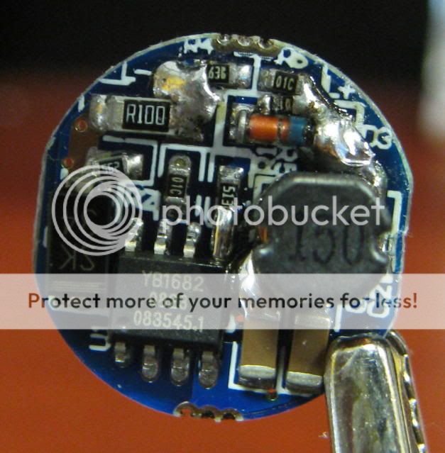
This is what they use now. The YB1682 buck IC is a 2A converter!
This is what they use now. The YB1682 buck IC is a 2A converter!
bigchelis
Flashlight Enthusiast
OP..
The G2 is plastic bodied, I would strongly suggest a multi mode drop in that way you can keep emitter temperatures in control.
IMHO you will overheat the LED running it at 1000-1400mah
A much safer route is to use lower drive currents.
My suggestion is to go with DX:11074 and use a 17670 cell in your G2. That way you can keep emitter temperatures down and extend run time.
Don't forget to mention with the 1.4A driver you got them to do over 200 out the front in the sphere of truth.
Kramer also put a 1.4A driver in my R2 Sacredfire 18650 light from DX ( SKU 17094) and it too puts out 206 lumens out the front now. Prior it was around 100ish lumens.
kramer5150
Flashaholic
Holy crap... they are trying to drive the XR-E with 2A !!! Thats crazy!
Actually... I pulled one of these from DX:11836 and the other came from DX:6090 (both are about 20 months old).
So they definitely started out using the same DC-DC boards. I was going to toss out these boards, but now I think I'll use them.
The old driver looks like the DX6090 driver. PT4105-based.
This is what they use now. The YB1682 buck IC is a 2A converter!
Actually... I pulled one of these from DX:11836 and the other came from DX:6090 (both are about 20 months old).
So they definitely started out using the same DC-DC boards. I was going to toss out these boards, but now I think I'll use them.
Last edited:
Justin Case
Flashlight Enthusiast
- Joined
- Mar 19, 2008
- Messages
- 3,797
It had been my understanding that the DX11836 and DX6090 had used the same driver. That's why I had previously favored the DX11836. However, I believe that there is at least a 3rd variant of the DX11836 driver. It is exactly like the DX6090 except that the resistor at R2 has a value of 0.2 ohms (marked R20), whereas it should be more like 0.28 ohms.
Your driver photo is a bit fuzzy. What is the writing on the resistor at R2 for the two boards (R2 is next to the diode marked SS14)? Is the resistor marked R20 or R220? Or even R27 or R28? How about the resistor at R1 for the two boards? Is it 1R0? Do you recall which board is the 11836 and which is the 6090 (and thus their corresponding resistor values)?
My measurements of the DX6090 driver are a little better than what some others have found on CPF. I get an LED power draw of about 3.3W in full regulation. The driver pulls about 4.3W, giving a driver efficiency of ~77%. Others have found efficiency closer to 2/3 (a combination of a lower Vf and a driver power consumption closer to 4.7W).
Close to 80% driver efficiency seems good to me for a cheap drop-in, especially given the driver's wide operating voltage range.
However, if you don't care about a wide voltage range, using a 3xAMC7135 driver board and 1xLi-ion will give you even better efficiency.
Last edited:
kramer5150
Flashaholic
R1 = 01Y for both boardsIt had been my understanding that the DX11836 and DX6090 had used the same driver. That's why I had previously favored the DX11836. However, I believe that there is at least a 3rd variant of the DX11836 driver. It is exactly like the DX6090 except that the resistor at R2 has a value of 0.2 ohms (marked R20), whereas it should be more like 0.28 ohms.
Your driver photo is a bit fuzzy. What is the writing on the resistor at R2 for the two boards (R2 is next to the diode marked SS14)? Is the resistor marked R20 or R220? Or even R27 or R28? How about the resistor at R1 for the two boards? Is it 1R0? Do you recall which board is the 11836 and which is the 6090 (and thus their corresponding resistor values)?
R2 = R20 for both boards
FWIW I do not recall which board came from which drop in.
What does this all mean?... that DX made significant board changes and the current 11836 is not what it used to be?
Justin Case
Flashlight Enthusiast
- Joined
- Mar 19, 2008
- Messages
- 3,797
R1 is a 1 ohm resistor. R2 is an 0.2 ohm resistor. R2 is the sense resistor and it is set for 1000mA output. 0.28 ohms would give 700mA, which is the paper recommendation according to the PT4105 datasheet (although the switch current limit is spec'ed at 1.3A).
Does the inductor have any markings on it?
For the new board I showed previously, it looks to me that the sense resistor network (R1 and R2) for the YB1682 has the wrong values, resulting in the wrong output voltage. To get 3.3V out, R1=6.2Kohms and R2=3.6Kohms. Instead, it looks like R1=51Kohms and R2=10Kohms. That sense resistor setup means the board is set to output at 7.5V. Changing R2 to a 30Kohm resistor should put the output back to 3.3V. Of course, that still doesn't fix the issue of the output current being 2A.
Last edited:
kramer5150
Flashaholic
R1 is a 1 ohm resistor. R2 is an 0.2 ohm resistor. R2 is the sense resistor and it is set for 1000mA output. 0.28 ohms would give 700mA, which is the paper recommendation according to the PT4105 datasheet (although the switch current limit is spec'ed at 1.3A).
Does the inductor have any markings on it?
For the new board I showed previously, it looks to me that the sense resistor network (R1 and R2) for the YB1682 has the wrong values, resulting in the wrong output voltage. To get 3.3V out, R1=6.2Kohms and R2=3.6Kohms. Instead, it looks like R1=51Kohms and r2=10Kohms. That sense resistor setup means the board is set to output at 7.5V. Changing R2 to a 30Kohm resistor should put the output back to 3.3V. Of course, that still doesn't fix the issue of the output current being 2A.
nope.. the inductors shown in my pics don't have any markings.
I bolded some of your comments above... Yikes 7.5V at 2A !!!!!
kramer5150
Flashaholic
The DX:11836 was introduced at ~$12.50, then about 4-5 months ago they dropped the price to the $9 range. I wonder if there is any correlation?
There is still hope for the 11836... but it requires some DIY power. DX has some really good (simple, efficient, reliable) 7135 boards for really cheap. Step up to a 17670 or 18650 cell and re-capture some of its former glory.
SKU:26108 (1050 mah)
SKU:26109 (1400 mah)
these are about as simple/reliable as you can design a DC circuit. Its just 7135 ICs wired in parallel, so you even have some degree of circuit redundancy built in. No multi-mode EPROM to fail.
Last edited:
Justin Case
Flashlight Enthusiast
- Joined
- Mar 19, 2008
- Messages
- 3,797
I used DX SKU 3201 (single mode, 3xAMC7135 driver) in an 11836 and that driver works well if you are willing to go with a single Li-ion for your power source.
It's a very easy mod. De-solder the driver from the brass pill. Pull out the driver from the pill. De-solder the two wires from the driver. Solder those wires to your new driver board. Insert the driver into the pill. Re-solder the driver to the pill. De-solder the spring from the 11836 driver. Solder the spring to the new driver. Add a solder blob to ground the driver board's outer trace to the brass pill.
In retrospect, I think that the DX11836 can be salvaged by replacing R2 with a 30Kohm resistor. I think that will fix the 2A issue. Assuming that the YB1682 is fixed at 3.3V output by using the correct sense resistor network values, the Cree R2 LED's Vf-If curve should then dictate that the current draw by the LED be around 0.9A-1A (a fairly typical value for a Vf of 3.3V). You can't force more current than the LED's Vf-If curve dictates for a given Vf. All you have to do is remove an SMT resistor and replace it with another one. I think I will try this out and save my supply of AMC boards.
Last edited:
Justin Case
Flashlight Enthusiast
- Joined
- Mar 19, 2008
- Messages
- 3,797
Here are input power vs input voltage plots for three different recent-vintage DX11836 Cree R2 drop-ins. For the second plot, I terminated the test early since the input current hit 2.3A at an input voltage of only 4.4V. I didn't want to cook the drop-in.
Here is a Power In vs Vin plot for an older DX11836, which appears to use the same driver as the DX6090. I measured ~75% driver efficiency.
And here is a Power In vs Vin plot for a DX6090:
Here is a Power In vs Vin plot for an older DX11836, which appears to use the same driver as the DX6090. I measured ~75% driver efficiency.
And here is a Power In vs Vin plot for a DX6090:
Last edited:
CampingLED
Enlightened
i.e what I love about the consistancy of the DX drivers . A modders dream AND nightmare. Many loose drivers have the same story to tell.
. A modders dream AND nightmare. Many loose drivers have the same story to tell.bshanahan14rulz
Flashlight Enthusiast
The old driver looks like the DX6090 driver. PT4105-based.
This is what they use now. The YB1682 buck IC is a 2A converter!
This is the driver that came with my 11836. I don't quite understand, though, you say it is putting out near 7V at 2.5A?! and which one of your input graphs correlate to this driver? Thanks!
Similar threads
Latest posts
-
-
-

-
 sofirn 3000mah 18650's - Good or bad?
- Latest: knucklegary
-

-

-
-
-

-
