homemade li-ion 14500 charger

Mugrunty

Newly Enlightened
Joined
Feb 12, 2007
Messages
163
Tada! I'm finaly done designing/building my own 14500 charger. I didn't feel like buying a charger that relies on the protection circuitry or simply overcharges the cells. My setup involves using an attiny861 microcontroller, a current sense resistor, and an n-ch MOSFET. The rest is mostly software and a few lesser compnents such as resistors, caps, and a 5v LDO regulator...oh and a two color led. I'll explain more of it when I'm not typing on my iPod and if someone is interested.

Basically it charges using CC/CV (400mA) and terminates when the current drops to around 60mA. The led is red while in the constant current stage, green while in the constant voltage stage, and off when done. If any errors show up, the light quickly alternates between green/red. Examples may be if someone put in an alkaline cell or if the cell is shorted, or if for any reason it's trying too hard to get current to flow and it's not flowing!

Since everything is controlled by the micro, it's easy to change everything from the charging current to the ending voltage to the ending current. I've thought about adding a stage where it has a pre-charge current incase the cell was really dead.(less than 3v).

Let me know what you think! Maybe I'll put up a schematic if I get one drawn. Or a pic!
 
Last edited:

Norm

Retired Administrator
Joined
Jun 13, 2006
Messages
9,512
Location
Australia
Sounds interesting, I'd be interested in the schematic, pre programmed PIC and if there was a board available that would be great.
Sounds like a great group project.
Norm
 

xenonk

Enlightened
Joined
May 3, 2009
Messages
327
I would definitely be interested in seeing this schematic and prototype. :thumbsup:
 
Last edited:

Mugrunty

Newly Enlightened
Joined
Feb 12, 2007
Messages
163
HA! A PIC... This is an ATMEL chip of course! :)

Tomorrow I'll have to draw up the schematic. You'll be shocked and amazed how little components it has. As of right now, its simply wired up on a radioshack board. It'd be nice to have it on a surfacemount board with traces though!

I'll post the code or send it as a .hex file or .asm file if anyone's really curious. It's pretty tiny. Only about 261 bytes!

It's still a prototype at the moment. But I plan on putting it in a box and giving it to my cousin. I got him a Quark and he also wanted a 14500 cell.

The only adapter he had was a PSP charger. (5.6V) So I designed this to run from that adapter! Pretty funny!
 

lolzertank

Enlightened
Joined
Dec 29, 2008
Messages
555
Location
The Land of Silicon
Let me try to guess the total number of parts (no wire, that's too hard). 1xAVR, 1xMOSFET, 3xCapacitor (I hope you bypassed the AVR...), 5xResistor and 1xLDO regulator. 1+1+3+5+1 = 11. Hmm, I guess you need 1xHeader for programming. 11+1 = 12. Wow!

Are you using high side or low side current sensing?
Have you thought about using USB to power your charger?

I think I can breadboard this... :twothumbs
 

Mugrunty

Newly Enlightened
Joined
Feb 12, 2007
Messages
163
Before I do up that schematic here is the part count. Pretty good guess lolzertank!

Resistors: 4
Caps: 3
LEDs: 1 bi-color
Micro: 1 ATtiny261/461/861
MOSFET: 1 N-ch
Regulator: LDO 5v
Button: 1 optional button for reset. (you know those paper clip ones? lol)

And of course a battery holder.

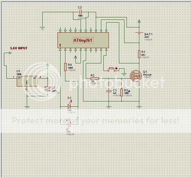
The current sense resistor is a 0.1 ohm and it's on the low side. So the battery goes in between +5v and the 0.1 ohm resistor. The 0.1 ohm resistor then goes to the drain of the FET. Source goes to ground.

It'll be easier to see one I get the schematic. And yes, there is a 0.1uF across the ADC analog power!
The other cap is a bulk cap for the regulator output. I might want one for the input as well.

The last cap is used in an ingenious way to allow the micro to control the mosfet in the linear region. (or anywhere in between!) This means you get REAL constant current control. Non of that crappy pulsing of current. That may be ok for NiCd/NiMH batteries, but I thought li-ion should have a real constant current. It's basically an RC circuit going to the gate of the FET. Varying the duty cycle going through the RC circuit, provides an output anywhere from 0vDC to 5vDC...this goes to the gate.

Yup. Everything else is software. I have it set up so that there are three constants you can change:

Current_limit: The maximum allowed current going to the battery
Voltage_limit: The point at which the micro switches to Constant voltage.
Current_end: The point at which the micro stops charging the battery

Currently, I have it set to approx 400mA charge, Voltage limit at 4.18V, and Current end at ~50mA.

Theoretically It has the capability to charge NiCds or NiMHs, but for now it throws an error if anything you put in there has less than 2.0V. (This includes shorting the leads)


Running off USB eh? Sounds pretty neat. It depends on how well regulated USB ports are. The problem I see is that the micro uses the +5V as a voltage reference for the ADC. If this was sagging to 4.8V or so under load, it would throw off the accuracy of the current sensing and voltage sensing. Plus, you would have to bypass the LDO regulator.

I might give it a try though!! Current wouldn't be a problem, IIRC USB ports allow 500mA.
 

lolzertank

Enlightened
Joined
Dec 29, 2008
Messages
555
Location
The Land of Silicon
I guess you could use a voltage divider and the internal reference. That brings up another question I have. How are you calibrating the ADC? From the AVR datasheet, the ADC looks like it might not be accurate enough for Li ion charging without calibration.

An interesting next step would be a SEPIC version of this. I'm not sure how you would go about making switching regulators with AVRs though.
 

Mugrunty

Newly Enlightened
Joined
Feb 12, 2007
Messages
163
I'm not sure what you mean by "not accurate enough". But it seems pretty good. Technically I have a voltage accuracy of 0.01960784313725490196078431372549 volts. So its not the best, but It holds it at 4.18V pretty dang good. I don't think the battery will care much if it moves around a little anyway.

I've also used the same micro to make a DC/DC boost converter circuit. It had an input of 1.5V to whatever the output was set to. It had a pot that you turned to set the output voltage. I used it as a 7V to 12V boost. It also worked pretty good on a single li-ion battery. But that's not important!
 

linterno

Enlightened
Joined
Dec 19, 2007
Messages
348
Running off USB eh? Sounds pretty neat. It depends on how well regulated USB ports are. The problem I see is that the micro uses the +5V as a voltage reference for the ADC. If this was sagging to 4.8V or so under load, it would throw off the accuracy of the current sensing and voltage sensing. Plus, you would have to bypass the LDO regulator.

I might give it a try though!! Current wouldn't be a problem, IIRC USB ports allow 500mA.
You could use the microcontroller's internal 1.1V / 2.56V voltage reference and a voltage divider instead of depending on external voltage.

From datasheet page 143 (doc2588.pdf from Atmel):

The voltage reference for the ADC may be selected by writing to the REFS2..0 bits in ADMUX.
The VCC supply, the AREF pin or an internal 1.1V / 2.56V voltage reference may be selected as
the ADC voltage reference. Optionally the internal 1.1V / 2.56V voltage reference may be decoupled
by an external capacitor at the AREF pin to improve noise immunity
Would be good to see your schematic and micro controller source code if you want to share it.

I might give it a try though!! Current wouldn't be a problem, IIRC USB ports allow 500mA.
And you could use two ports in parallel to get 1000mA.
 
Last edited:

Mugrunty

Newly Enlightened
Joined
Feb 12, 2007
Messages
163
I was aware of the different voltage references available, but I chose Vcc as a reference for a couple of reasons. I knew that I would have a rock solid 5V for a reference, and that it would help reduce the amount of components I would need. It works well when measuring a li-ion battery because it is inbetween 0v-5v. Usually around 3v-4.2v.

I didn't need it for the sense resistor either because of the built in gain available in the ADC. I used a unipolar differential reading with a gain of 32x.
This meant that I could read current values as low as about 6mA and as high as 1.56A (with about a 6mA accuracy). Again this is all with no more dividing resistors that may need tweaking or 1%. This is also only using 8-bits of the 10-bit ADC. I figured 8-bits was enough accuracy for this application and I didn't have to fool around with the software required to use all 10-bits.

I could always use the full 10bits and then have a current reading from roughly 1.5mA - 1.56A. Or Voltages from 0.0048 - 5v.

Eh, too many possibilities. But you're right, Everything would work a little better using the 1.1V reference, but I didn't feel like adding any more components. (EDIT: plus the current setup works great when using the regulator. Your Idea would work well when using USB ports as power)

About the source code, whats the best way of doing that? Just copy and paste it here? Or somehow host the .asm file? (Yeah, did it in Assembly language! :p)
I still haven't drawn up that schematic! Too much stuff today. I'll get it up ASAP!

:)
 
Last edited:

FoxyRick

Newly Enlightened
Joined
Dec 6, 2005
Messages
95
Location
Cold Wet England
Sounds fun! I was thinking of this myself over the last week or so, since it costs so much to get a good charger in the UK. A look at the schematic and software would be good.

Atmel though... I've got drawers full (literally) of Microchip and TI MCU's and not a single Atmel!
 

Mugrunty

Newly Enlightened
Joined
Feb 12, 2007
Messages
163
What the heck is wrong with atmel??? I dunno, its all I've ever used really. They seam great, run at basically 1 instruction per clock cycle, use almost no power, and seem to do anything I'd ever want ever! But, I've never really used a PIC. It'd probably take a little while getting used to the different instruction set of the PIC.

And, the place I work only use ATMEL as well...so yup. I'm a little used to ATMEL! :)


And ok, I'll start the schematic. But where do I put the code!?? I could put it here but it'd look funny.
 

Mugrunty

Newly Enlightened
Joined
Feb 12, 2007
Messages
163
Lets see how this looks...Sorry for the crudity of the schematic. I did it quick and wasn't used to the program.

Li-ioncharger.jpg


And here is the code... Again sorry if it looks goofy.

Code:
.include "tn861def.inc"

.DEF    TEMP    =    R16
.DEF    DUTYHI    =    R17
.DEF    DUTYLO    =    R18
.DEF    DUTY    =    R19
.DEF    VOLT    =    R20
.DEF    CURRENT =     R21
.DEF    TEMP2    =    R24
.DEF    TEMP3    =    R25

.DEF    TIME1    =    R22
.DEF    TIME2    =    R23

.EQU    CURRENT_LIMIT = 0x40 ;(0x41 = 400mA)
.EQU    VOLTAGE_LIMIT = 0xDA ;(0xD5 = 4.176V)
.EQU    CURRENT_END      = 0x01 ;(0x07 = 42.89mA)
                             ;(0x06 = 36.76mA)
                             ;(0x05 = 30.64mA)
.EQU    DUTY_HIGH_TIME= 0x50


.ORG 0x0000 rjmp RESET ; Reset Handler
;rjmp EXT_INT0 ; IRQ0 Handler
;rjmp PCINT ; PCINT Handler
;rjmp TIM1_COMPA ; Timer1 CompareA Handler
;rjmp TIM1_COMPB ; Timer1 CompareB Handler
;rjmp TIM1_OVF ; Timer1 Overflow Handler
;rjmp TIM0_OVF ; Timer0 Overflow Handler
;rjmp USI_START ; USI Start Handler
;rjmp USI_OVF ; USI Overflow Handler
;rjmp EE_RDY ; EEPROM Ready Handler
;rjmp ANA_COMP ; Analog Comparator Handler
;rjmp ADC ; ADC Conversion Handler
;.ORG 0x000C rjmp WDT ; WDT Interrupt Handler
;rjmp EXT_INT1 ; IRQ1 Handler
;rjmp TIM0_COMPA ; Timer0 CompareA Handler
;rjmp TIM0_COMPB ; Timer0 CompareB Handler
;rjmp TIM0_CAPT ; Timer0 Capture Event Handler
;rjmp TIM1_COMPD ; Timer1 CompareD Handler
;rjmp FAULT_PROTECTION ; Timer1 Fault Protection

RESET:
        RCALL INIT
        RCALL DELAY

START:    RJMP CHG_CC
        

CHG_CC:

        RCALL PWM                ;START DUTY CYCLE PULSE (LOW %)
        RCALL GET_CURRENT
        CPI CURRENT,CURRENT_LIMIT;CHECK CURRENT FOR CURRENT LIMIT
        BRLO UP1                ;IF LOWER, INCREASE CURRENT
        BREQ CONTINUE1            ;IF AT LIMIT, DO NOTHING
        BRSH DOWN1                ;IF TOO HIGH, DECREASE CURRENT
UP1:    CPI DUTY,0xFF            ;LIMIT MAX DUTY CYCLE TO FF (PREVENTS ROLL OVER)
        BREQ ERROR                ;NEW! IF DUTY CYCLE IS THIS HIGH, SOMETHING IS WEIRD

        INC DUTY
        RJMP CONTINUE1
DOWN1:    DEC DUTY
        RJMP CONTINUE1
CONTINUE1:    
        SBI PORTB,1
        CBI PORTB,0        ;LIGHT UP LED RED FOR CC
    

        RCALL GET_BATTVOLT
        CPI VOLT,0x66        ;~2.0V
        BRLO ERROR    ;SOME IDIOT PUT A NON-LITHIUM BATTERY IN THE CHARGER!!
        CPI VOLT,VOLTAGE_LIMIT;HAS BATTERY REACHED VOLTAGE LIMIT (~4.2v)
        BRLO CHG_CC                ;IF NO, STAY IN CONSTANT CURRENT STAGE
        RJMP CHG_CV            ;VOLTAGE LIMIT REACHED, GO TO CONTANT VOLTAGE


CHG_CV: SBI PORTB,0
        CBI PORTB,1        ;LIGHT UP GREEN LED FOR CV

        RCALL PWM
        RCALL GET_BATTVOLT
        CPI VOLT,VOLTAGE_LIMIT
        BRSH VOLT_REG    ;IF VOLTAGE TOO HIGH, DECREASE CURRENT A LITTLE
        RJMP CHG_CV    ;CONTINUE CHARGING IF VOLTAGE IS FINE
VOLT_REG:
        DEC DUTY
        RCALL GET_CURRENT
        CPI CURRENT,CURRENT_END    ;IF CURRENT IS LOWER THAN END CURRENT
        BRLO CHG_DONE            ;STOP CHARGING
        RJMP CHG_CV                ;OTHERWISE KEEP GOING


CHG_DONE:CBI PORTB,0
        CBI PORTB,1    ;TURN OFF LED TO INDICATE DONE
        CBI PORTB,6    ;TURN OFF MOSFET
        SLEEP        ;SLEEP (DRAWS ALMOST NO CURRENT)
        RJMP CHG_DONE


ERROR:
        CBI PORTB,6;TURN OFF MOSFET
        SBI PORTB,0
        CBI PORTB,1
        RCALL DELAY
        RCALL DELAY
        RCALL DELAY
        SBI PORTB,1
        CBI PORTB,0
        RCALL DELAY
        RCALL DELAY
        RCALL DELAY
        RCALL GET_BATTVOLT
        CPI VOLT,0x75
        BRSH START
        RJMP ERROR
;*******************************************************************
INIT:
        LDI DUTY,0x01    ;START DUTY CYCLE LOW
        SBI DDRB,0    ;MAKE LED PORTS AN OUTPUT 
        SBI DDRB,1
        SBI DDRB,6    ;MAKE MOSFET OUTPUT
        
        CBI PORTB,6    ;TURN MOSFET OFF
        LDI TEMP,0x30
        OUT ADMUX,TEMP    


        LDI TEMP,0x30    ;MAKE SLEEP=POWER DOWN
        OUT MCUCR,TEMP
    
        
        RET


GET_BATTVOLT:    ;MAKES TWO READINGS TO MAKE SURE IT'S CORRECT
        LDI TEMP,0x2D    ;VCC AS REF, DIFFERENTIAL INPUT ON (PA5 +, ANND PA6 -)
        OUT ADMUX,TEMP    ;SET STUFF AGAIN
        LDI TEMP,0x08    ;SET UP AS GAIN OF X1 AND THE MUX5 BIT FOR ABOVE
        OUT ADCSRB,TEMP

        LDI TEMP,0xC5
        OUT ADCSRA,TEMP    ;START A CONVERSION
CHK:    SBIS ADCSRA,6    ;WAIT FOR END OF CONVERSION
        RJMP CHKDONE
        RJMP CHK
CHKDONE:                ;DISCARD FIRST CONVERSION
        LDI TEMP,0xC5
        OUT ADCSRA,TEMP    ;START A SECOND CONVERSION = NEEDED BECAUSE I CHANGED REFERENCES.
CHK4:    SBIS ADCSRA,6    ;WAIT FOR END OF CONVERSION
        RJMP CHKDONE4
        RJMP CHK4
CHKDONE4:

        IN VOLT,ADCH    ;MOVE READING INTO BATT REG
    
        RET


GET_CURRENT:
        LDI TEMP3,0x0A
        LDI TEMP,0x30
        OUT ADMUX,TEMP    ;SET UP DIFF ON PA6+ AND PA7- WITH GAIN OF 32X
        LDI TEMP,0x48
        OUT ADCSRB,TEMP    ;SET UP GAIN OF 32X AND MUX5 OF ABOVE

        LDI TEMP,0xC5
        OUT ADCSRA,TEMP    ;START A CONVERSION
CHK2:    SBIS ADCSRA,6    ;WAIT FOR END OF CONVERSION
        RJMP CHKDONE2
        RJMP CHK2
CHKDONE2:
        LDI TEMP,0xC5
        OUT ADCSRA,TEMP    ;START A SECOND CONVERSION
CHK3:    SBIS ADCSRA,6    ;WAIT FOR END OF CONVERSION
        RJMP CHKDONE3
        RJMP CHK3
CHKDONE3:
    ;    DEC TEMP3
    ;    CPI TEMP3,0x01
    ;    BRSH CHKDONE2    ;RUN 10 TIMES DANGIT! WHATS WRONG WITH THIS!?

                        ;FINAL END
        IN CURRENT,ADCH    ;MOVE READING INTO BATT REG
    
        RET


PWM:
    
    LDI DUTYLO,0xFF
    MOV DUTYHI,DUTY    ;MOVE REQUESTED DUTY CYCLE INTO MEMORY FOR PWM HI
    SUB DUTYLO,DUTYHI    ;TAKE 255-REQUESTED DUTY CYCLE --> DUTYLO
    LDI TEMP2,DUTY_HIGH_TIME;EX: 50% DUTY CYCLE = 127  255-127=128
                        ;HIGH=127 LOW=128 --> TOTAL:255
    
    
PHIGH:
    NOP                ;GIVE MORE DUTY CYCLE HIGH
    DEC TEMP2
    CPI TEMP2,0x01
    BRSH PHIGH

    SBI PORTB,6
    LDI TEMP2,DUTY_HIGH_TIME
    DEC DUTYHI
    CPI DUTYHI,0x00
    BREQ PLOW
    RJMP PHIGH

PLOW:CBI PORTB,6
    DEC DUTYLO
    CPI DUTYLO,0x00
    BREQ PWMDONE
    RJMP PLOW

PWMDONE:
    RET


DELAY:
        LDI TIME2,0xFF
LOOP2:    LDI TIME1,0xFF

LOOP:    DEC TIME1
        CPI TIME1,0x00
        BRNE LOOP
        DEC TIME2
        CPI TIME2,0x00
        BRNE LOOP2
                        
        RET
 

Mugrunty

Newly Enlightened
Joined
Feb 12, 2007
Messages
163
Hey look at that! It's in a window with a scroll bar! Thats pretty neat, didn't know you could do that! Anyway, I never really changed the comments on the code, that was only for me. Never really finished it up and made it look nice, so sorry if it is confusing. I'm sure I can explain anything in it.

Some of the comments are not extremely accurate. Example, Having current_end set at 0x01 is really about 50mA for some reason.
 

Mugrunty

Newly Enlightened
Joined
Feb 12, 2007
Messages
163
Yeah um...I had a period of agrivation when the current sense reading wasn't working right... I fixed it so running 10 samples probably isn't necessary anymore.
 

csshih

Flashlight Enthusiast
Joined
Sep 21, 2008
Messages
3,950
Location
San Jose, CA
Hey look at that! It's in a window with a scroll bar! Thats pretty neat, didn't know you could do that!

now if only I had the equipment to implement this stuff.
:thumbsup: regardless! I'm sure someone else will find it useful!
 
Top