• You must be a Supporting Member to participate in the Candle Power Forums Marketplace.

    You can become a Supporting Member.

Sold/Expired I need some interest to build/sell my custom lights

LEDobsession

Enlightened
Joined
Oct 30, 2008
Messages
507
Location
Northern Utah
Ok. Im back from Canada and Im officially trying to do a little test market with these. I want to make 10 or so (I can probably sell 2 to a buddy), so maybe a total of 12.

DSC_1296.jpg


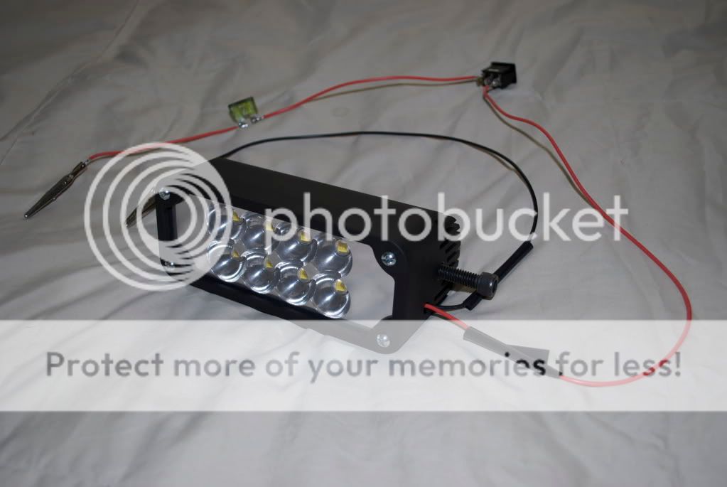
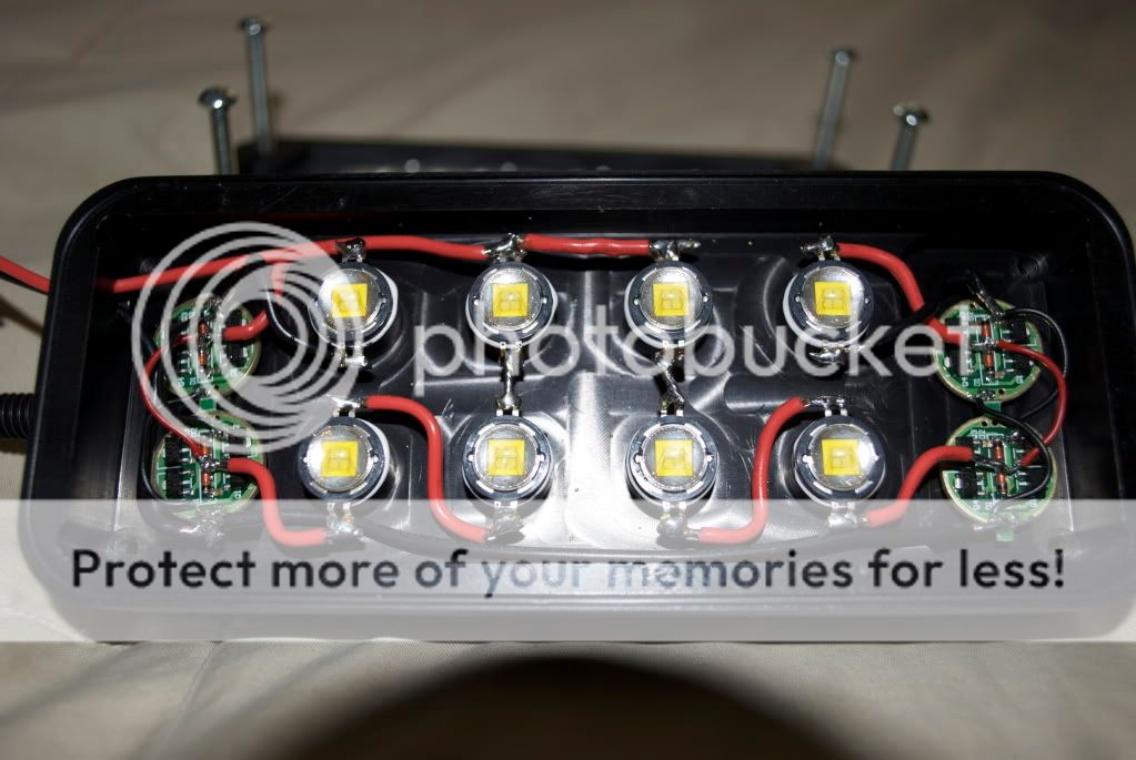
This light, being the first and technically my prototype, will be somewhat altered for production. The fins, wiring connection, reflectors/optics, water sealing, etc. will be what Im changing. Nothing too major but enough to put it to where I would be very comfortable in the position of selling them.

What I really need to know is, how many people would very seriously be interested in purchasing one.

The cost I'm aiming for is US $600.00 for a 6 inch light using 8 Seoul Semiconductors P7 Series emitter producing (my guess) 7000 lumens.

They will be Black Anodized (unless you would like to pay the extra for color anodizing) and will most likely have my Logo - Solaris Series by Insane Lighting - laser engraved on the anodizing and possibly "Custom Built by Trevor Hirschi espesially for __name__". If you have anything else you would want lasered on, you could email me the text/image of your choice and I can have it engraved on for a little extra (whatever by buddy charges me for it).

If there is enough interest, I will provide as much specifications as I possibly can at the current time.

So, my question is, Who wants one?


Trevor Hirschi
Insane Lighting


Moderators: I had no idea where to put this.
 

LEDobsession

Enlightened
Joined
Oct 30, 2008
Messages
507
Location
Northern Utah
Heat wise it leveled off at 79-80 C after 20 minutes on 14 volts. That was stationary. When I make more, I wont do so much of a radius on the back so therefore it will have more fin length/surface area. They'll run warm but within junction temperatures and when the vehicle is moving, there will be added cooling from that as well. :thumbsup:
 

LEDobsession

Enlightened
Joined
Oct 30, 2008
Messages
507
Location
Northern Utah
LEDobsession - That is a very nice light setup. Very impressive 8 x approx 10 watts / led output and power consumption. What is your design input voltage?

It is a neat light - outside of my budget, but I like it.

Thanks Harry. Input voltage is 12-15 VDC.
 

LEDobsession

Enlightened
Joined
Oct 30, 2008
Messages
507
Location
Northern Utah
Are you thinking of these as car / truck mount LED based "off road" lights, or more of a bike light?

Offroad use, so, truck, jeep, 4-runner, etc.. My original intended use was for my 2005 Honda TRX450R Sport quad, but for use on an ATV/Dirtbike, you would need a higher output stator so I never ended up using it on mine (although it woulda been freakin sweet).

If you're interested in beamshots and you havent already seen the build, check out page 4 of that thread.
 

spencer

Enlightened
Joined
Jan 19, 2008
Messages
785
Location
Saskatoon, Canada
What are the dimensions of the light and would you sell it without any guts (LED's, Drivers, Reflectors)? I would still want the lens, O-rings, etc.
 

Justin Case

Flashlight Enthusiast
Joined
Mar 19, 2008
Messages
3,797
Heat wise it leveled off at 79-80 C after 20 minutes on 14 volts. That was stationary. When I make more, I wont do so much of a radius on the back so therefore it will have more fin length/surface area. They'll run warm but within junction temperatures and when the vehicle is moving, there will be added cooling from that as well. :thumbsup:

At what point did you measure the 79-80C? Heat sink fins? Solder point? Assuming the latter as a best case, the 3C/W thermal resistance of a P7 would suggest that the junction temp is at least about 110C. If the 79-80C figure of merit is the temp at the fins, then junction temp is going to be even hotter. The moving vehicle should help, but if you operate in 35C ambient vs 25C room temp, that adds an additional load on the system. I would verify that your junction temp is compatible with good long term lumens maintenance (which typically means 80C junction temp max), not just merely staying under the 140C junction temp absolute limit spec.
 

LEDobsession

Enlightened
Joined
Oct 30, 2008
Messages
507
Location
Northern Utah
What are the dimensions of the light and would you sell it without any guts (LED's, Drivers, Reflectors)? I would still want the lens, O-rings, etc.

Length=6.25", Height=2.5", Depth=2.75"
That is just my prototype. If I end up using some Sekonix optics, the height and possibly length (length wouldnt necessarily need to be extended) will increase slightly to accommodate the 1.5" Dia of the optics. Im not sure about selling just an encasement yet. I guess I could but I would prefer the whole. The price would be around ~400 for encasement only.

At what point did you measure the 79-80C? Heat sink fins? Solder point? Assuming the latter as a best case, the 3C/W thermal resistance of a P7 would suggest that the junction temp is at least about 110C. If the 79-80C figure of merit is the temp at the fins, then junction temp is going to be even hotter. The moving vehicle should help, but if you operate in 35C ambient vs 25C room temp, that adds an additional load on the system. I would verify that your junction temp is compatible with good long term lumens maintenance (which typically means 80C junction temp max), not just merely staying under the 140C junction temp absolute limit spec.

I used a surface mount thermocouple with alumel and chromel conductors and measured the temp as close to the die as I could get. I dont recall what the temp was on the fins but it was a little higher. But the temp as close to the dies as I could get to leveled off around 80 C (the highest I saw was 82).

:thumbsup:
 

Justin Case

Flashlight Enthusiast
Joined
Mar 19, 2008
Messages
3,797
Sounds like the solder point temp.

I personally would be concerned about excess heating of the LED junction. Presumably, you made your thermocouple measurement indoors at room temp. In the world, ambient temp could be much hotter, leading to a corresponding increase in solder point temp and hence junction temp. LED reliability as a function of junction temp obeys an Arrhenius relationship and going from the usual 80C junction temp for 70%/50,000 hr lumens maintenance to 110C or higher junction temp could result in drastically reduced lumens maintenance life. The difficulty is that the datasheets don't seem to provide good data on estimating the reduction in hours. Now, maybe it won't matter anyway if you aren't going to operate the device for even 1000 hours over its lifetime.

The second issue is based on the link you provided that describes the light as for offroad racing. I don't know if I would trust thermal epoxy to hold the LEDs under those conditions. Granted, it looks like your reflector plate provides mechanical pressure on the P7's case to hold it in place. So it does seem very hard to imagine how the LED could break free from the epoxy if there is no vertical movement. Maybe from very slight lateral movement over time that fatigues and eventually fractures the epoxy. If the epoxy breaks free, you've lost your thermal path even if the LED itself stays in place.

I probably would have designed a slightly recessed cup for each P7's slug to sit in and use thermal compound under each P7. Then I'd use epoxy to glue the circumference of each LED. Then use the reflector plate as a secondary mechanical method to secure the LEDs. Now, if the epoxy breaks, it doesn't matter since the thermal compound stays in-place (it has moderate viscosity) to provide its thermal path. The recess also helps to constrain the LED from lateral movement, which could help prevent the epoxy from breaking loose. The reflector plate constrains any out-of-plane movement. In addition, thermal compound has much better thermal conductivity than thermal epoxy, giving you that much better heat sinking.
 
Last edited:

LEDAdd1ct

Flashlight Enthusiast
Joined
Jul 4, 2007
Messages
3,557
Location
Hudson Valley
I'd love one of these to bike with, but unfortunately, $600 is way above my reach. A three LED model putting out over 2,000 lumens would totally rock and (hopefully?) be much cheaper. 2,000 lumens would be plenty for riding a bike.
 

LEDobsession

Enlightened
Joined
Oct 30, 2008
Messages
507
Location
Northern Utah
Sounds like the solder point temp.

I personally would be concerned about excess heating of the LED junction. Presumably, you made your thermocouple measurement indoors at room temp. In the world, ambient temp could be much hotter, leading to a corresponding increase in solder point temp and hence junction temp. LED reliability as a function of junction temp obeys an Arrhenius relationship and going from the usual 80C junction temp for 70%/50,000 hr lumens maintenance to 110C or higher junction temp could result in drastically reduced lumens maintenance life. The difficulty is that the datasheets don't seem to provide good data on estimating the reduction in hours. Now, maybe it won't matter anyway if you aren't going to operate the device for even 1000 hours over its lifetime.

The second issue is based on the link you provided that describes the light as for offroad racing. I don't know if I would trust thermal epoxy to hold the LEDs under those conditions. Granted, it looks like your reflector plate provides mechanical pressure on the P7's case to hold it in place. So it does seem very hard to imagine how the LED could break free from the epoxy if there is no vertical movement. Maybe from very slight lateral movement over time that fatigues and eventually fractures the epoxy. If the epoxy breaks free, you've lost your thermal path even if the LED itself stays in place.

I probably would have designed a slightly recessed cup for each P7's slug to sit in and use thermal compound under each P7. Then I'd use epoxy to glue the circumference of each LED. Then use the reflector plate as a secondary mechanical method to secure the LEDs. Now, if the epoxy breaks, it doesn't matter since the thermal compound stays in-place (it has moderate viscosity) to provide its thermal path. The recess also helps to constrain the LED from lateral movement, which could help prevent the epoxy from breaking loose. The reflector plate constrains any out-of-plane movement. In addition, thermal compound has much better thermal conductivity than thermal epoxy, giving you that much better heat sinking.

Wow. Food for thought.

Im kinda wondering if I were to change the thermal path a little, if that would help. What I mean is this:
DSC_1301.jpg

Take a look at how the Emitters are raised quite a bit from the base (kinda hard to tell here) as a whole. If I were to recess them a little, as you mentioned, I would think that the heat is going to be removed a little faster. Now, my plans for new ones was going to be- flush mount them (I hadnt thought of recessing), and for 2 reasons. The one being that I would most likely be using optics instead of reflecters, and 2, to help lighten it up a little bit. But now Im thinking that it would also create better thermal path as the little pedestal was sort of acting as a heat bank somewhat with the small diameter that had surface area inside. Im not too sure. I just havent seen that any of the companies that engineer these do what I did. They're all flush mounted. So Im hoping that that would help also.

I had never even thought of thermal epoxy strength. I figured it was just there forever, I mean, look at that stuff. It says permanent all over it. I also didn't know that the thermal compound was any better for thermal conductivity. I had assumed that it wasnt as reliable for strength as well (?).

You should note, the process to building one of these lights is very, um, consuming. Ive learned a ton of important aspects in building this light. All of this for example. Remember that I havent even built the a production part yet and Im still working on all my design work. I want to be able to design, manufacture, and sell these and know I can count on them. Im also not an engineer of any sort, in fact, Im just a 20 year old machinist who has an LED obsession and wants to share that with the rest of the people on this forum that also share that hobby. Im learning and I want to do everything I can to make this powerful, reliable, and affordable to the people who enjoy this technology. :thumbsup:

Oh, I forgot, I took the temp measurements outside in Utah (it was about 82 F at the latter part of the evening). It was running off of 14 VDC from my idling truck.

I'd love one of these to bike with, but unfortunately, $600 is way above my reach. A three LED model putting out over 2,000 lumens would totally rock and (hopefully?) be much cheaper. 2,000 lumens would be plenty for riding a bike.

It would be cheaper but I never really designed anything for bikes. Never even crossed my mind. I would've had to come up with some sort of battery pack that has a run time. I dont like run times. I like solid power. Something that is more maintenance-free, I guess. Haha
 

Justin Case

Flashlight Enthusiast
Joined
Mar 19, 2008
Messages
3,797
Wow. Food for thought.

Im kinda wondering if I were to change the thermal path a little, if that would help. What I mean is this:
DSC_1301.jpg

Take a look at how the Emitters are raised quite a bit from the base (kinda hard to tell here) as a whole. If I were to recess them a little, as you mentioned, I would think that the heat is going to be removed a little faster. Now, my plans for new ones was going to be- flush mount them (I hadnt thought of recessing), and for 2 reasons. The one being that I would most likely be using optics instead of reflecters, and 2, to help lighten it up a little bit. But now Im thinking that it would also create better thermal path as the little pedestal was sort of acting as a heat bank somewhat with the small diameter that had surface area inside. Im not too sure. I just havent seen that any of the companies that engineer these do what I did. They're all flush mounted. So Im hoping that that would help also.

I had never even thought of thermal epoxy strength. I figured it was just there forever, I mean, look at that stuff. It says permanent all over it. I also didn't know that the thermal compound was any better for thermal conductivity. I had assumed that it wasnt as reliable for strength as well (?).

You should note, the process to building one of these lights is very, um, consuming. Ive learned a ton of important aspects in building this light. All of this for example. Remember that I havent even built the a production part yet and Im still working on all my design work. I want to be able to design, manufacture, and sell these and know I can count on them. Im also not an engineer of any sort, in fact, Im just a 20 year old machinist who has an LED obsession and wants to share that with the rest of the people on this forum that also share that hobby. Im learning and I want to do everything I can to make this powerful, reliable, and affordable to the people who enjoy this technology. :thumbsup:

Oh, I forgot, I took the temp measurements outside in Utah (it was about 82 F at the latter part of the evening). It was running off of 14 VDC from my idling truck.

Don't get me wrong. I think you've done a great job and you have a very cool project.

Epoxy is very strong. But bonding to aluminum can be less than optimal, depending on the specific epoxy. Adding in alumina also can weaken the bonding vs. epoxy without alumina.

I've been able to pop of emitters that were glued on using Arctic Alumina thermal adhesive (epoxy). Other times, I destroyed the emitter. Maybe they were glued slightly differently -- one with the exact 50-50 recommended mix of the two parts, the other not at 50-50. Who knows.

My suggestion to consider using thermal compound is simply for the better thermal conductivity and the viscous nature of the compound. It isn't for adhesion. That comes from the epoxy that I suggested to use around the circumference of the emitter's case.

I'm not saying my way is right. It is just another way to consider.

The take-away is to identify the optimum mounting method and design so that nothing ever falls off.
 

LEDobsession

Enlightened
Joined
Oct 30, 2008
Messages
507
Location
Northern Utah
Don't get me wrong. I think you've done a great job and you have a very cool project.

Epoxy is very strong. But bonding to aluminum can be less than optimal, depending on the specific epoxy. Adding in alumina also can weaken the bonding vs. epoxy without alumina.

I've been able to pop of emitters that were glued on using Arctic Alumina thermal adhesive (epoxy). Other times, I destroyed the emitter. Maybe they were glued slightly differently -- one with the exact 50-50 recommended mix of the two parts, the other not at 50-50. Who knows.

My suggestion to consider using thermal compound is simply for the better thermal conductivity and the viscous nature of the compound. It isn't for adhesion. That comes from the epoxy that I suggested to use around the circumference of the emitter's case.

I'm not saying my way is right. It is just another way to consider.

The take-away is to identify the optimum mounting method and design so that nothing ever falls off.


That sounds good. Ill have to acquire some thermal compound too.
Thanks for your input, Justin. I really appreciated it. Im constantly learning on here. :thumbsup:
 

LEDAdd1ct

Flashlight Enthusiast
Joined
Jul 4, 2007
Messages
3,557
Location
Hudson Valley
I'd love one of these to bike with, but unfortunately, $600 is way above my reach. A three LED model putting out over 2,000 lumens would totally rock and (hopefully?) be much cheaper. 2,000 lumens would be plenty for riding a bike.

It would be cheaper but I never really designed anything for bikes. Never even crossed my mind. I would've had to come up with some sort of battery pack that has a run time. I dont like run times. I like solid power. Something that is more maintenance-free, I guess. Haha

I think it would be easier than you think. :grin2: You don't have to come up with a battery pack at all. Leave the power supply to the end-user. If you spec it to run off 12 volts, I'll grab a 12 volt pack; if you spec it for a 14.4/14.8 volt pack, I'll grab a pack with that voltage. I'll take care of the maintenance/charging. I would absolutely *love* three LEDs with excellent heatsinking, putting out at or just below 2,000 lumens. If we assume 700 lumens apiece, 700*3 = 2,100 lumens, which I think is very reasonable.

If you (pretty please) decide to build a prototype in that size/form factor, I would be delighted to field test it. A shorter/more compact housing would be just the ticket.
 

snarfer

Enlightened
Joined
Feb 21, 2008
Messages
241
I bet you could considerably improve thermal performance of this light by crosscutting the fins, making sure all your fin-to-fin spaces are approximately 1/4", reducing the baseplate thickness to about 3/16", and flushmounting the LEDs.
 

LEDobsession

Enlightened
Joined
Oct 30, 2008
Messages
507
Location
Northern Utah
I think it would be easier than you think. :grin2: You don't have to come up with a battery pack at all. Leave the power supply to the end-user. If you spec it to run off 12 volts, I'll grab a 12 volt pack; if you spec it for a 14.4/14.8 volt pack, I'll grab a pack with that voltage. I'll take care of the maintenance/charging. I would absolutely *love* three LEDs with excellent heatsinking, putting out at or just below 2,000 lumens. If we assume 700 lumens apiece, 700*3 = 2,100 lumens, which I think is very reasonable.

If you (pretty please) decide to build a prototype in that size/form factor, I would be delighted to field test it. A shorter/more compact housing would be just the ticket.

I will definitely keep that in mind. I hadn't really thought of the other sports requiring light but Im sure the market for them could easily be as good or better than what I had intended upon. I may just have to get into that market as well.

I bet you could considerably improve thermal performance of this light by crosscutting the fins, making sure all your fin-to-fin spaces are approximately 1/4", reducing the baseplate thickness to about 3/16", and flushmounting the LEDs.

You bring up an interesting point there. I have never known what is better for the heat dissipation for fins. Are vertical or horizontal fins better for this application? Is more fins closer together better, or is less fins farther apart better? On one hand, more and closer together will provide more surface area but being closer also could provide more heat trap. (The more/less Im referring to is in a set dimension where the fins have to fit within.) Less fins and farther apart would be just the opposite. Less fins, therefore less surface area but farther apart to increase airflow bethween. Cross cutting fins has also been a mystery to me but it seems to be used quite often so it must help quite a bit. I've never known anything of the thermodynamic properties of fins so Ive been in the dark.
 

Latest posts

Top