georges80
Flashlight Enthusiast
I have a thread in the bike subforum, but I know a lot of folk here don't visit it too often.
So, as a short teaser:
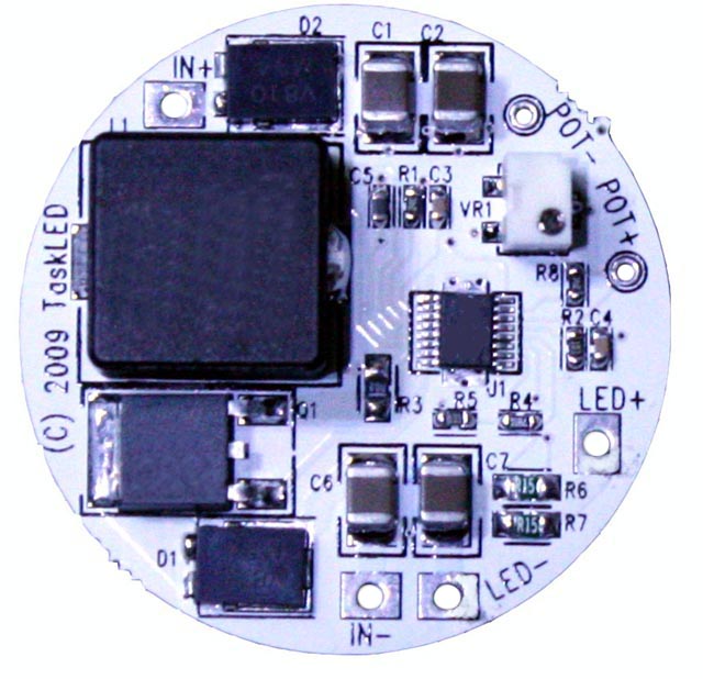
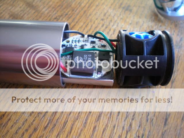
1.4" diameter, single sided components, designed to use thermal pad material to mount to a heatsink.
8 - 50V input, up to 80V output (open circuit protected). Maximum output current 1.3A (adjustable via 11 turn trimpot onboard or used in conjunction with an external 50K pot).
Boost converter, approx 90% efficient for most input/output ranges.
Reverse polarity protected.
Recommended max input current 5A.
cheers,
george.
So, as a short teaser:
1.4" diameter, single sided components, designed to use thermal pad material to mount to a heatsink.
8 - 50V input, up to 80V output (open circuit protected). Maximum output current 1.3A (adjustable via 11 turn trimpot onboard or used in conjunction with an external 50K pot).
Boost converter, approx 90% efficient for most input/output ranges.
Reverse polarity protected.
Recommended max input current 5A.
cheers,
george.

")