This is really a simplified explanation, this subject is complex but basically, if the actual LED light emitting area is shaped like a square, then many reflectors will focus an "image" of that square. If you are getting a square image of a square LED light emitting area, that is actually kind of GOOD. A good reflector acts kind of like a projector lens or camera lens in that it projects an image of the light source. :candle:

With spotlights, flashlights, etc., a small point source light is desirable to produce a thin far traveling beam. Incandescent filaments are often in somewhat long and rectangular configurations. That is why some incandescent spotlights and flashlights have a kind of rectangular beam...because the filament is sometimes mounted perpendicular to the light beam, and the reflector projects the image.

Most LED reflectors are deep and are front 'firing' because unlike HID or incandescent light sources which radiate the light in almost all directions, an LED radiates or projects it's light in a 180 degree sphere or forward only. Now remember much of the area of most small reflectors is so close to the light source itself, it will not make a sharp or well focused image. That is one of the reasons why most lights make a 'round' spot...:thumbsup:
LED light sources work well with large (sometimes spherical), lenses which gather and focus most of the LED light into a beam. I have seen these types of LED flashlights, and they definitely project a 'square' image of the square LED light emitter.

Keep up the good work.:thumbsup: Check out my threads:
"24 inch Homemade Searchlight Reflector" and my
"50 inch Monster Searchlight". There might be some information throughout the pages that can shed some light (knowledge) on this subject.:wave: One way to find these threads, is to go to "Big Lights" and scroll down near the bottom of the list.
Cheers
LightSward
Quick method of designing your own reflector. LED lights only use the reflector from the front of the light source "F" forward. You can photo copy this and play with the zoom in and out, to get a "Quick" design.
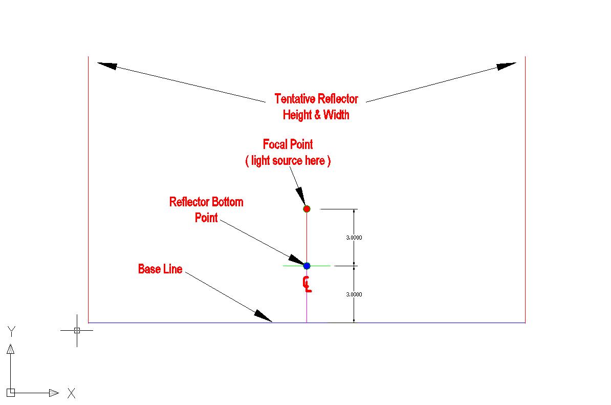
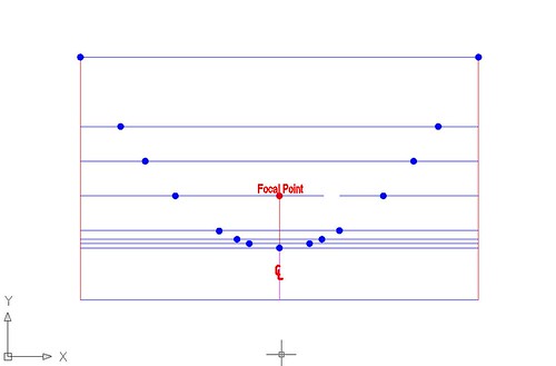
Here is a basic CAD layout to design your own Parabolic Reflector.
CAD Parabolic Instructions
First determine the basic parameters of the Parabolic Reflector. Bulb type, size of light emitter, desired beam configurations, use, costs and many more factors determine the size and basic dimensions of the reflector. Deep Dish or Shallow Mirror, storage, manufacturing ability, etc., then draw base line, focus point and bottom point of reflector..
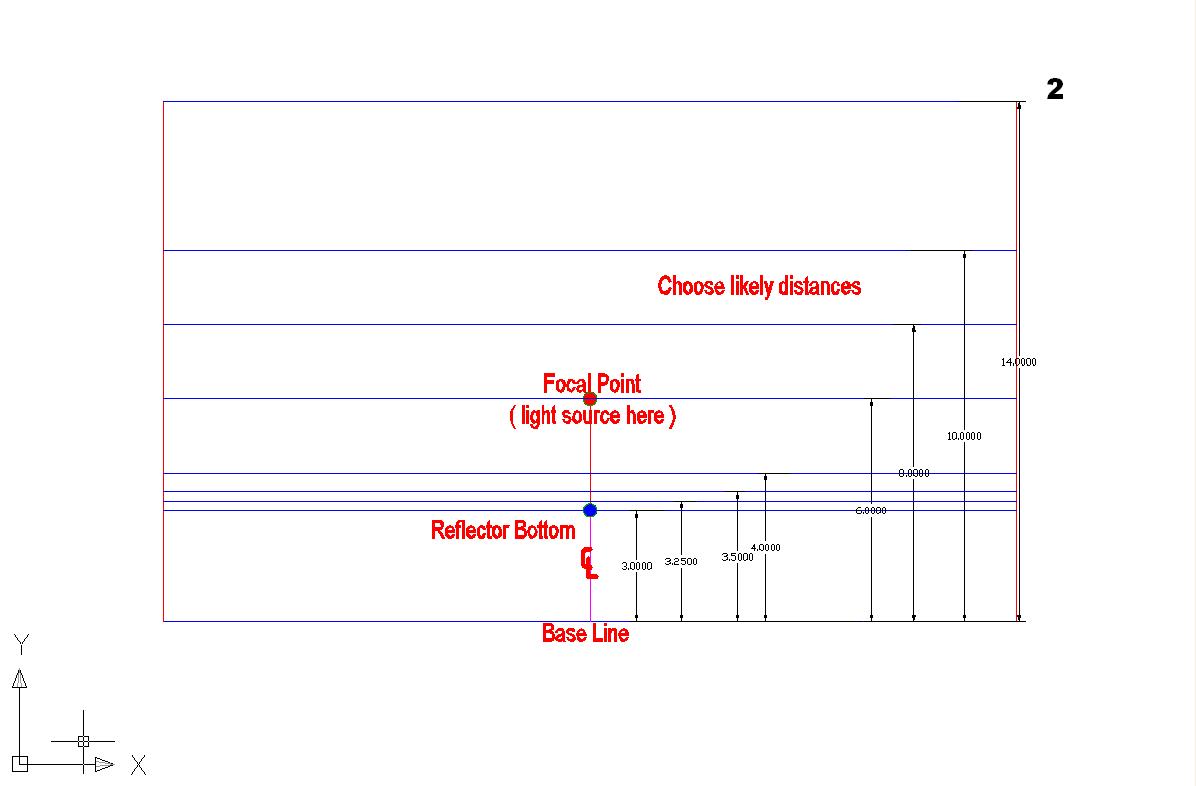
Draw lines that will help you form the shape of the parabolic reflector. If you want a shallow mirror type reflector, you need most of your parallel lines close to the bottom, you may have to try a little trial and error. You should quickly realize what spacing you'll need.
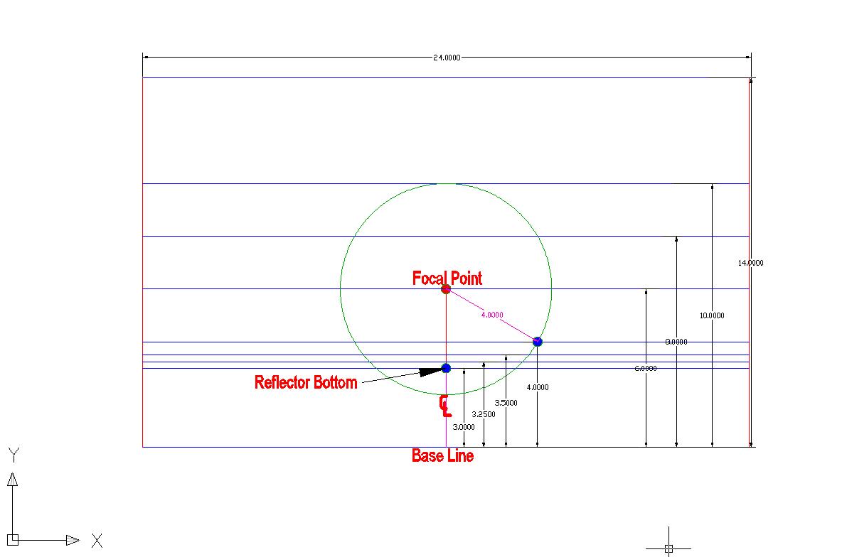
Draw circles, radius equals selected parallel line distances from the base line. Where circle intersects line (at two points) place a dot at each intersecting point for line/ circle pair only.
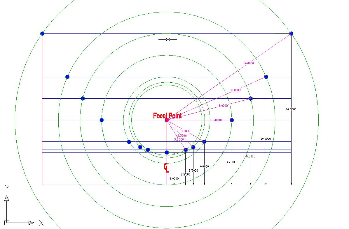
Finish intersection and dot placements.
Remove circles. :twothumbs
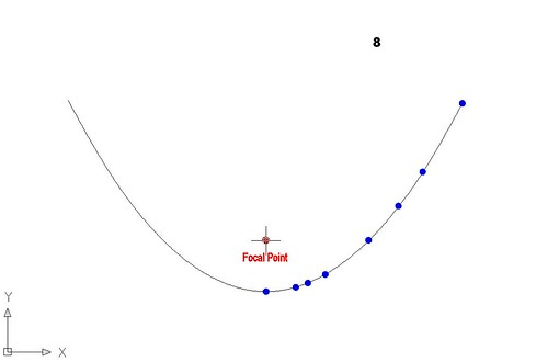
Remove parallel lines. Connect the dots, In CAD use spline or polyline function. By hand, connect the dots using a 'french' curve, finished
You can also just copy and paste this curve and zoom in and out to get the right size.
In Conclusion:
(Need to edit)
Basically, one of the easiest and quickest methods use is the "model T method" After determining requirements and the light source characteristics, the overall size of reflector is determined. I draw an up side down "T" (or sideways), with the horizontal line length equal to the desired reflector diameter. The horizontal portion of the upside down "T" is called the 'base' line. I then draw 6 parallel lines to the base line, each parallel line distance from the base line, is a fraction of the depth of the eventual reflector.
The first parallel line is drawn half way between the focal point and the base line. This will be the closest part or bottom of the reflector. The top or furthest line from the base line is the top of the reflector or farthest part from the light source. Then I draw circles with the center at the focal point. The circle's radius is equal to the distance a chosen parallel line is from the "T" horizontal base line. As an example: if the top line is 10 inches from the base line, then draw a 10" radius (20" diameter) circle with the center at the focal point. The 10" radius circle will cross the #10" line at two points. place a dot at each of these two points. This is where the top of the reflector is.
Next if you drew a line 5" from base line, then draw a 5" radius circle with it's center at the focal point. Repeat for the other lines. You will see the basic shape of the parabola. If you need...draw more lines at more intervals. Eventually the points are connected with a french curve used to draw the parabolic shape. If using AutoCAD, the polyline or p-line function then converted to spline works very well. There are easy mathematical formulas as well. I use the above method, because for me, I can draw an accurate parabola in very little time!
I hope this helps. I am working on new designs all the time!:twothumbs