Installing a Rocker Switch in a Mag.....a continuation (Pic Heavy!)

mrartillery

Enlightened
Joined
Mar 24, 2007
Messages
987
Location
north carolina
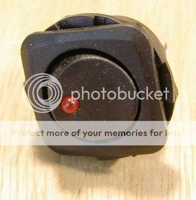
A couple of years back there was a thread here about how to install a high amperage rocker type switch in a Mag D housing. The only problem was there was no instruction or pictures on how to go about wiring it. So I recently went by Radio Shack and bought a few of these and installed one in of my my Mag housings and would like to share with everyone who had questions about it, exactly how i done mine. Im using mine for my Mag458 which is currently underway! :naughty:

I would like to apologize in advance for the picture quality, my camera doesnt like close ups. :sick2:

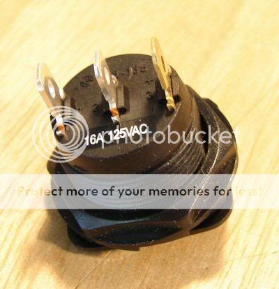
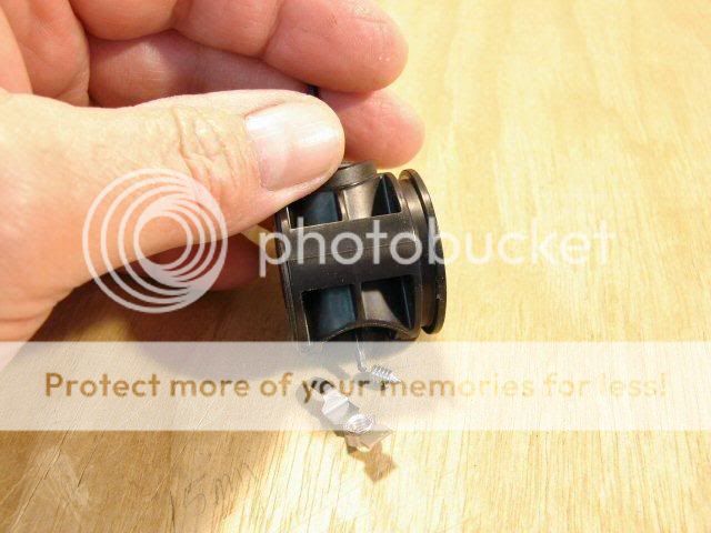
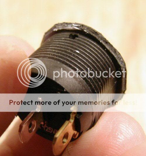
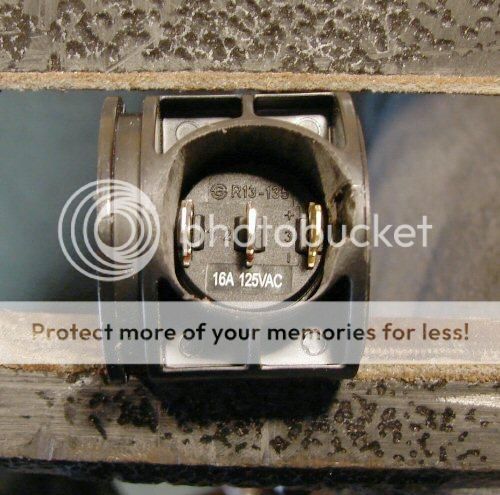
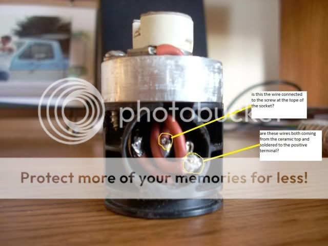
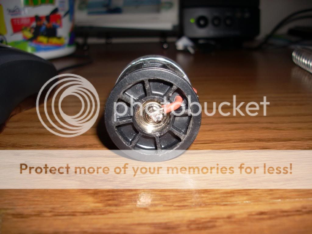
Here is the back side of the switch, wires soldered directly to switch terminals.
guns012.jpg


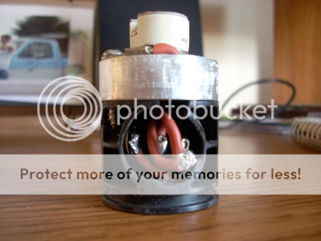
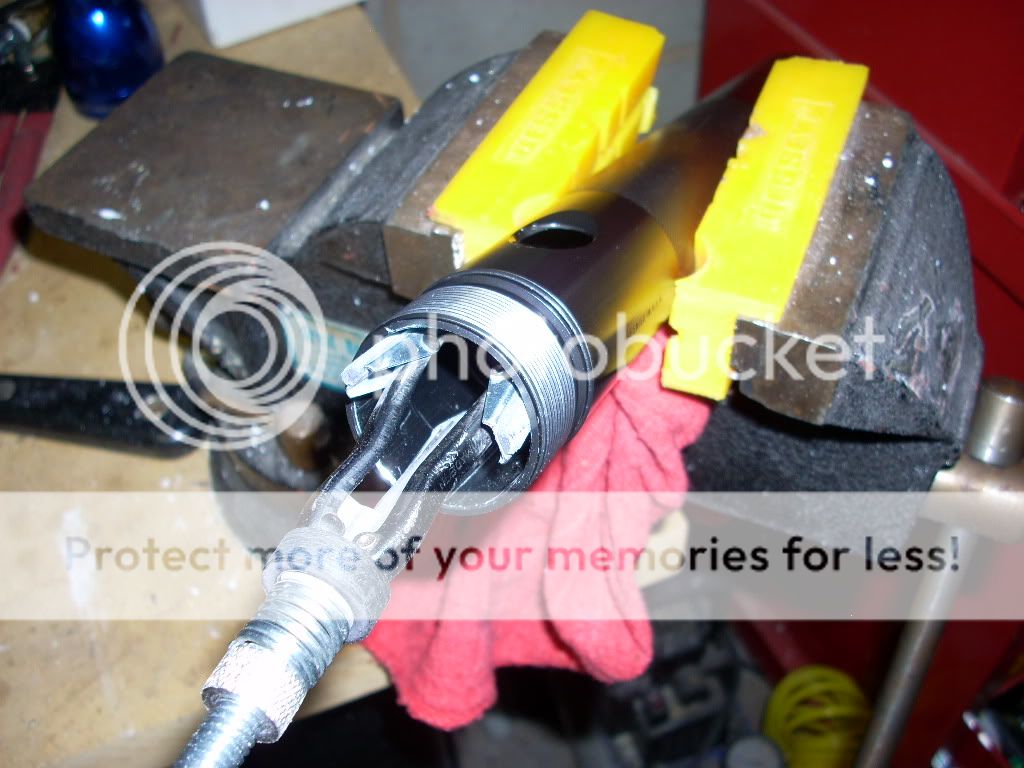
The ground which is soldered in with wire from KIU, grounded on the base of the KIU.
guns013.jpg


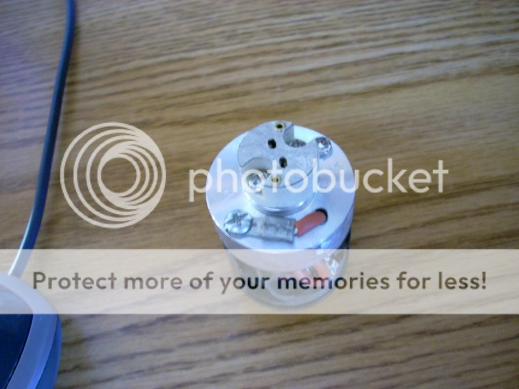
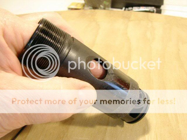
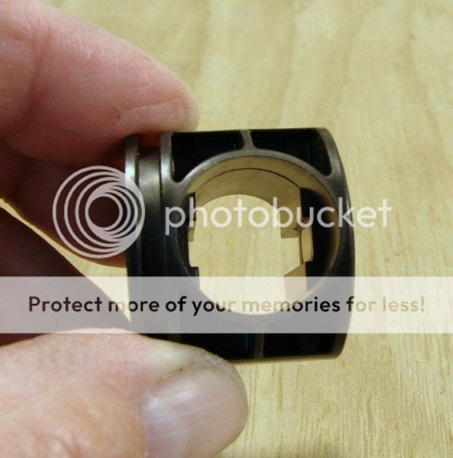
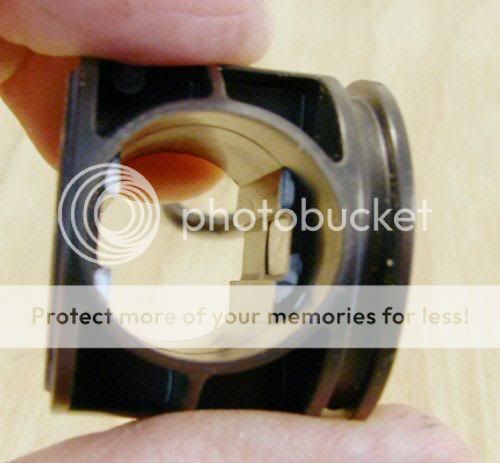
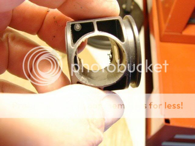
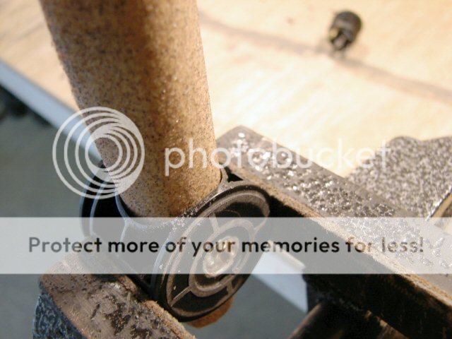
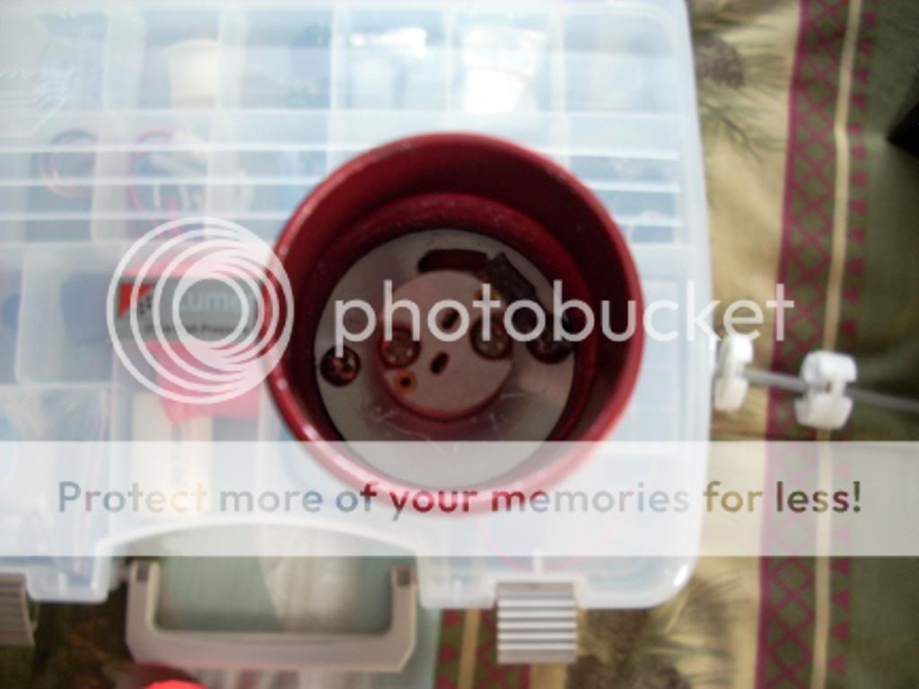
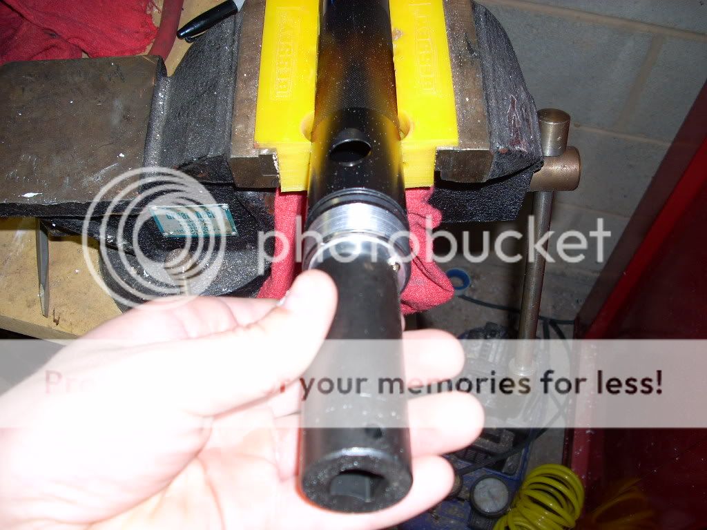
A look down its throat
guns011.jpg
 
Last edited:

mrartillery

Enlightened
Joined
Mar 24, 2007
Messages
987
Location
north carolina
Re: Installing a Mag Rocker Switch.....a continuation

The end results
guns006.jpg

guns014.jpg

guns015.jpg

guns016.jpg


A few of you might be wondering why one of them if red and one is blue, well i put the completed switch in a 2 cell just to verify operation, the red one in the 458.

***UPDATE***

This is also a must that I didnt add the first go around, so here it is: you will need to remove about a inch of ano above the switch hole for a good grounding surface for the KIU, Ive found is best to do with a brake cylinder hone as seen here.

guns024.jpg


This is what it should look like after completion with the hone

guns025.jpg


I also slightly off set the KIU base on the switch, this will give a much tighter fit inside the mag tube, which will require a small amount of grinding to the KIU and I like to use a 22mm deep socket and a rubber mallet to tap it in to place. Push it down slightly past the hole and then apply your epoxy, then slide the switch back in to position through the bottom of the tube.

guns026.jpg
 
Last edited:

^^Nova^^

Enlightened
Joined
Aug 4, 2008
Messages
388
Location
Australia
Re: Installing a Rocker Switch in a Mag.....a continuation

Nice work on the switch. Did you remove any anno from inside the tube where the kiu sits to get a good ground or was it fine "stock"? How did you hold the kiu and switch in place?

To help with the pics, take a photo from further away and then crop the image down to the required size for the forums. This will zoom into the part you want and you don't lose quality either. The camera will focus better from slightly further away so you end up with pics the same size but looking much better.

Cheers,
Nova
 

mrartillery

Enlightened
Joined
Mar 24, 2007
Messages
987
Location
north carolina
Re: Installing a Rocker Switch in a Mag.....a continuation

Nice work on the switch. Did you remove any anno from inside the tube where the kiu sits to get a good ground or was it fine "stock"? How did you hold the kiu and switch in place?

To help with the pics, take a photo from further away and then crop the image down to the required size for the forums. This will zoom into the part you want and you don't lose quality either. The camera will focus better from slightly further away so you end up with pics the same size but looking much better.

Cheers,
Nova

Oh cool, thanks for the camera advice, ill have to remember that!:cool: 
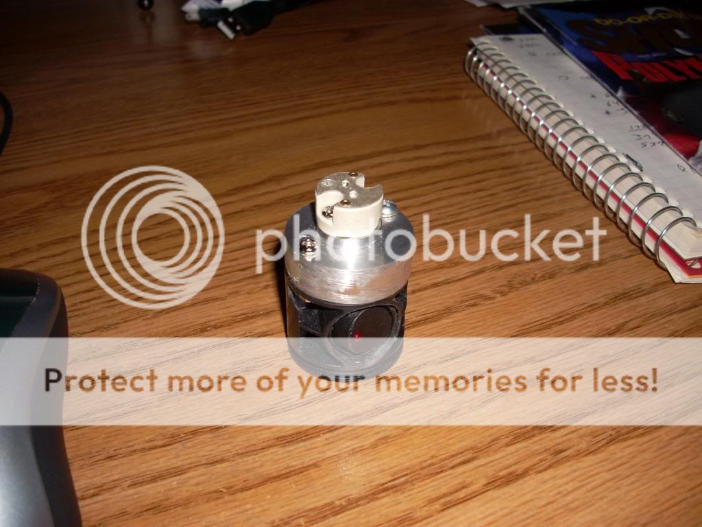
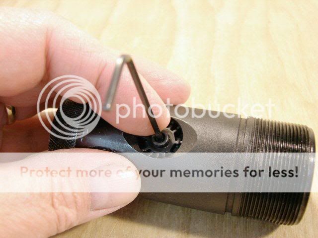
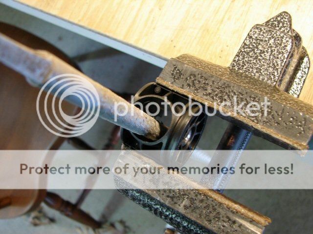
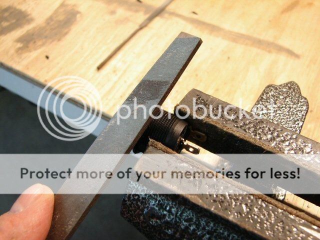
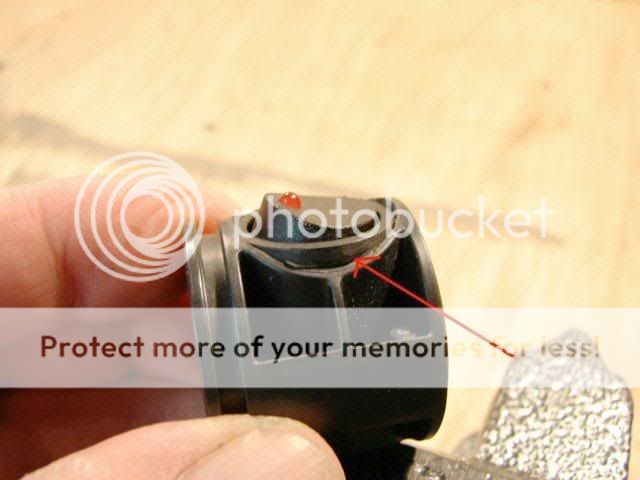
As for removing the ano, no i didnt when i tested it on the Mag11 and it worked fine, actually got .22 more volts out of it than a stock KIU modded mag switch. But I'm goin to sand down the inside a little bit before installing it in the 458, and to hold it in place, its already fairly tight, but im going to use a couple drops of 2 part epoxy to hold it firmly in place.

*Picture quality somewhat updated*
 
Last edited:

Databyter

Enlightened
Joined
Oct 12, 2005
Messages
525
Location
San Diego
Re: Installing a Rocker Switch in a Mag.....a continuation

Compliments of Aircraft800 who revived pics on old rocker thread (scroll down).

This is a show-post with the tutorial including pics.

https://www.candlepowerforums.com/posts/3101853&postcount=16.

And Paste thanks to original author Jusval,..

Originally Posted by jusval
Hello,
I had a couple people ask "Exactly how do I use a Rocker switch in a Mag "D" switch body?". So I thought it would be nice to show everyone how I do it, with details and photos.

The idea is to use an economical and readily available switch (15A-30A) to replace the Stock Mag switch. Something easy, that only takes a few simple hand tools and not a lot of electronics (for dummies like me). Also to use a switch that still maintained the stock placement and stock rubber cover.

Well, I found that rocker switches from Radio Shack, or the local Auto Parts Store, would work for this purpose. The one I am using is a 16A 125V switch from radio shack. I have seen 20A and 30A in Auto parts stores.

I will go thru the whole replacement, step by step. I know some of this may be redundant.

First I am using an old cut off "D" body, that's all I had lying around.

Here's the switch
1.jpg

2.jpg


I just use two fingers and pinch the rubber cover, to take it out.
3.jpg


The exposed switch.
4.jpg


5/32" Allen wrench inside the switch, I loosen the set screw it about 6 turns.
5.jpg


Pushing out the switch. It should slide out easy after you push it out a little ways.
6.jpg


This is an old switch that I cut the bulb tower off of. If you need to cut the tower off, just use a hacksaw.
7.jpg


I use the same allen wrench to push out the set screw and the negative terminal.
8.jpg


Push out the switch, from the bottom side of the housing.
9.jpg


The four flat areas that need to be removed, inside the housing.
10.jpg


The reason why they need to be removed. The new switch won't clear.
11.jpg


I dabbed white out on the areas to be removed.
12.jpg


My fancy tools. 3 round files.
13.jpg


I start with the larger coarse file. An even larger one would work well. I just want to make the housing completely round.
14.jpg


Pretty much done roughing it out. The metal contact plate does not come out, just the plastic surrounding. The rocker switch has 2 flat spots on it and they slide over the metal plate.
15.jpg


Now I modify the rocker switch. I need to remove the square edges and get it round. I use a pair of cutters at first, but I just cut a little at a time, or the plastic splits instead of cutting.
16.jpg


After using the cutters. I get fairly close that way.
17.jpg


More special tools, a couple flat files.
18.jpg


I finish removing the material and round it off using the files like this. Not much pressure on the vise or you break the switch.
19.jpg


Final touch is with a sanding block.
20.jpg


That's about finished. I just need to clean off the burrs.
21.jpg


Now the rocker fits in the housing fairly well. It's still just a bit too tight.
22.jpg


I can use sandpaper to take a little more out of the housing, just a fine adjustment or two.
23.jpg


I don't want that little raised red light, so I file it off flush.
24.jpg


Now I am seeing how it goes into the body and I will need to do some angle trimming here.
25.jpg


Making sure the rocker is down flush with the housing edge.
26.jpg


Now I use my small flat file to take off the edges and conform to the housing angle.
27.jpg


Just a shot of the underside. I can just drill a hole in the ends of the housing for wires to go thru and solder them on.
28.jpg


Nice fit! Slides right in. Put the toggle in the "on" position, so it slides in and if you take it out, put it in the "off" position to slide it back out.
29.jpg


The housing is in place. Now I usually hold it in place by putting a little JB Weld on the top of the housing, where it touches the "C" ring inside the body. That will be enough to hold it, when it sets up.
30.jpg


Rubber cover is back in place and it looks stock once again.
31.jpg


EDIT: Use a bit of 5 minute 2 part epoxy in a couple of spots on the underside, just to keep the switch from moving around. You can break free "just a dab" if need be, to remove the switch again. Also do the same thing with the whole housing, to the "C" ring, with just a couple dabs of epoxy.


I hope this helps someone out in their search for mods.


:goodjob: MrArtillary

P.S. To Moderator - If too picture heavy delete pic paste and just keep show-post link. Thanks!
 
Last edited:

mrartillery

Enlightened
Joined
Mar 24, 2007
Messages
987
Location
north carolina
Re: Installing a Rocker Switch in a Mag.....a continuation

Compliments of Aircraft 800 who revived pics on old rocker thread (scroll down).

This is a showpost with the tutorial including pics.

https://www.candlepowerforums.com/posts/3101853&postcount=16.

:goodjob:

Thanks for adding that DB, now the post is complete! :D

*Edit* I would also like to add that instead of installing mine vertically like the tutorial, i found that there was a little more room to operate if you install it horizontally.
 
Last edited:

Databyter

Enlightened
Joined
Oct 12, 2005
Messages
525
Location
San Diego
Re: Installing a Rocker Switch in a Mag.....a continuation

I'm inspired, I'm thinking of making some of these. I have 3 Mag switches to Mod. Several friends have expressed interest in a slightly less expensive version of some of my lights, i.e. no soft start switch, no body boring (longer Mags).

It will be nice to have a few ready for whatever (like my own Mag 458 Build when I can afford all the junk for it)
 

mrartillery

Enlightened
Joined
Mar 24, 2007
Messages
987
Location
north carolina
Re: Installing a Rocker Switch in a Mag.....a continuation

Lol, glad i could help inspire you :twothumbs, I also have the same thing in mind as well. I plan on making another one of these within the next week or so for a upcoming 623 build. It just takes a little patience to get everything to fit together but you can do it! Also, i dont know if anyone can really tell by the pic or not, but the ground has a modified spade connector that i cut the long tail off of and soldered the two leads to, this seemed to work better than trying to solder the wires on top of one another.
 

Dave 88

Newly Enlightened
Joined
Jun 9, 2009
Messages
14
Re: Installing a Rocker Switch in a Mag.....a continuation

I just spent 20 minutes typing a reply only to have the system tell me I am not logged in !! Its too late to work on that again. :thumbsdow I am going to sleep!
 

rayman

Flashlight Enthusiast
Joined
May 6, 2008
Messages
1,219
Location
Germany
Re: Installing a Rocker Switch in a Mag.....a continuation

Installed a Rocker switch yesterday in my 3D Maglite. I also had to make it fit with by using a dremel and then I glued it in with adhesive. Fo the GND I had another idea than you. As I'm using the KD 32650 which are a little bit to small in the diameter for the Maglite body I used telfon wire and soldered it directly to the tailcape spring. Now I have a good solid connection and the batteries won't rattel ;). I'm not finish yet but I will post pictures of it.

rayman
 

Dave 88

Newly Enlightened
Joined
Jun 9, 2009
Messages
14
Re: Installing a Rocker Switch in a Mag.....a continuation

Ok so back to what my idea was.

Instead of modding the stock mag switch I was thinking of using some PVC tubing instead. Take a piece that will fit the switch and use a hole saw to cut it leaving the ends rounded. Then another that is the same ID as that mag tube and cut a hole into that so the other slides into it. This is just to set it to the height to hit the ring and could be cut very short. You would still have to bevel the edges of the switch so it fits, but gluing it into the tube would be easy. Cut a hole at the bottom of the PVC so you can put a screw with a rounded nut as the (+) connection, as well as a hole at the top.

For the (-) connection I was thinking of just deanodizing the top of the mag as well as the top outer edge of the heatsink. Then just drill a hole at the bottom of the heatsink to solder a wire to and that should take care of the (-) connection.

Not sure if the first part would be easier, but you would end up with a little more room for drivers than with the stock switch.
 

mrartillery

Enlightened
Joined
Mar 24, 2007
Messages
987
Location
north carolina
Re: Installing a Rocker Switch in a Mag.....a continuation

Ok so back to what my idea was.

Instead of modding the stock mag switch I was thinking of using some PVC tubing instead. Take a piece that will fit the switch and use a hole saw to cut it leaving the ends rounded. Then another that is the same ID as that mag tube and cut a hole into that so the other slides into it. This is just to set it to the height to hit the ring and could be cut very short. You would still have to bevel the edges of the switch so it fits, but gluing it into the tube would be easy. Cut a hole at the bottom of the PVC so you can put a screw with a rounded nut as the (+) connection, as well as a hole at the top.

For the (-) connection I was thinking of just deanodizing the top of the mag as well as the top outer edge of the heatsink. Then just drill a hole at the bottom of the heatsink to solder a wire to and that should take care of the (-) connection.

Not sure if the first part would be easier, but you would end up with a little more room for drivers than with the stock switch.

Is something like this what you had in mind?
guns017.jpg


And the bottom view..
guns018.jpg


Im not trying to steal your glory or your idea by no means, but ive drawn this out several times in my head and have been working on so called "prototype' so to speak for quite some time now. Granted, this is rough idea of what it would look like, the pvc coupler will need to be cut down, the bottom plug will have to be cut down and epoxied into place as well as the top plug which will need to be cut down and epoxied. Also i was planning on using a Judco type push button switch for this build all being self contained within the pvc housing. The bottom will have metal slug protruding so it can be used with flat top IMR's.

Any of you that are familiar at all with plumbing have already noticed that this is the hot/cold water pipe which is bigger than standard 1" pvc, i did this on purpose, so I could hand fit the core into the housing for a tighter fit.
 

Dave 88

Newly Enlightened
Joined
Jun 9, 2009
Messages
14
mrartillery - no worries I have no plans to make these to sell.

That is something like what I am thinking. I am working with an SST-90 so the bi-pin base is not something I am factoring in. Just drill into that for a switch. My idea just uses another piece of pvc that would to 90* into something like that to hold the switch.

As for any mods I have been working with the stock switch some more. I made but need to install a copper ring for the middle of the switch. I don't know if its going to conduct better than the aluminum one, but worth a shot. I also have the two u-shaped bits that contact the ring covered with a thin coat of solder to help them conduct better as well as some desoldering braid balled inside them. Hard to describe that, but its just in where the top and bottom contact points are. So far with 3 Tenergy Nimh D cells I see 9 amps when they are freshly charged on the SST90. :cool:
 

crewsy

Newly Enlightened
Joined
Apr 26, 2010
Messages
23
gday mrartillery,
hope all is well!
excuse my lack of knowledge, I have here an edited version of your picture above showing the wiring.
rockerswitchwiring-1.jpg

Could you please confirm that what I have stated on it is correct or not.
If not, could you please explain?
Thanks in advance mate :)
 

mrartillery

Enlightened
Joined
Mar 24, 2007
Messages
987
Location
north carolina
gday mrartillery,
hope all is well!
excuse my lack of knowledge, I have here an edited version of your picture above showing the wiring.
rockerswitchwiring-1.jpg

Could you please confirm that what I have stated on it is correct or not.
If not, could you please explain?
Thanks in advance mate :)

Sure no problem, the first question (middle terminal) this is NOT connected to the ground terminal on the KIU base, this is however connected to a lead from the KIU, the middle position is the load terminal of the rocker, the terminal that delivers the current to the bulb basically.

Secondly, the furthest one to the right are both ground wires, one coming from the screw on the base of the KIU and the other going into the socket of the bi pin. Hope this helps!
 
Last edited:

ama230

Enlightened
Joined
Apr 23, 2010
Messages
416
Location
Mesa, Arizona
great work man, great to see a successful project. Also its different than whats out there too. So KUDOS:thumbsup:
 

hawkz

Newly Enlightened
Joined
Dec 11, 2005
Messages
98
Location
San Diego
Hey man. I'm trying to do this mod as well. But I don't understand how the ground works. How do I get the negative end to connect with the switch? Looks like you just have a wire hanging and barely making contact with the body :(
 

mrartillery

Enlightened
Joined
Mar 24, 2007
Messages
987
Location
north carolina
Hey man. I'm trying to do this mod as well. But I don't understand how the ground works. How do I get the negative end to connect with the switch? Looks like you just have a wire hanging and barely making contact with the body :(

In the picture above (which was the first one of these i ever done) I used a spade flag connector with the two wire leads soldered together, however I have found in the builds since it is easier and actually holds better if solder one ground lead to the switch terminal and then solder the second lead on top of it, looks and holds much better IMO. Also, it doesnt ground here by the wire touching the body, it grounds through the KIU base, which when I mount it to the switch i mount it slightly off center that way i have to fit the switch to the mag tube for a tighter fit, I also remove the ano with a brake cylinder hone about a inch above the switch hole, this will provide a much better grounding surface. Ive been meaning to add this to the thread and will whenever I do another build.
 
Last edited:
Top