NANJG 101-AK 1400mA 3-mode driver

brted

Enlightened
Joined
May 16, 2009
Messages
345
Location
Atlanta, GA
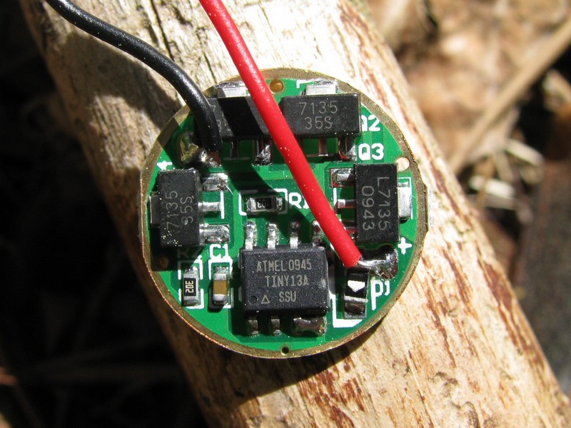
I got one of these today from Shining Beam. This is a 3-mode version. DX sells a 16-mode version where modes are in 3 groups (one of which is 3 modes) and the DX one is missing one of the 7135's.

I notice that the SB version uses a newer ATMEL chip than the DX version (TINY13A instead of TINY13V) and that the two lower right legs of the ATMEL chip seem to be bridged. I wonder what would happen if those were not bridged? Would it become like the DX chip? If you bridged the legs of the DX chip, would it be fixed in 3 modes like this one? I know ATMEL chips can be programmed differently, but these two drivers even have the same model number.

I haven't had a chance to install this in anything since I am waiting to use it with an XP-G LED that I haven't gotten yet. But here's a picture.


At DX:

http://www.dealextreme.com/details.dx/sku.7612

At ShiningBeam

http://www.shiningbeam.com/servlet/the-133/**NEW**-3-dsh-Mode-Regulated-Circuit/Detail
 

Black Rose

Flashlight Enthusiast
Joined
Mar 8, 2008
Messages
4,626
Location
Ottawa, ON, Canada
I have a couple of these drivers, along with a pair of XP-G R4s - all coming from Shiningbeam.

I will be putting one driver and an XP-G R4 in a DX sku 15687 DIY flashlight body kit.

The other is to repair/upgrade the DX XP-G single mode drop-in I bought that self destructed (LED separated from the MCPCB :ohgeez:).
 

Black Rose

Flashlight Enthusiast
Joined
Mar 8, 2008
Messages
4,626
Location
Ottawa, ON, Canada
I installed this driver in a DX DIY kit (Aurora V6) today with an XP-G R4.

Driver and LED were both bought from Shiningbeam.

With an AW 2200 mAh protected 18650, current draw at the tail:
Code:
Mode      Current
Low       60 mA
Medium    440 mA
High      1420 mA

With a pair of Titanium Innovations CR123A cells, current draw at the tail:
Code:
Mode      Current
Low       80 mA
Medium    450 mA
High      1420 mA

Medium mode whines whether powered by a Li-Ion cell or a pair of CR123A cells.

Memory works well most of the time.
Sometimes it will come on in the same mode as when shut off. Other times it will come on in the next mode.

EDIT: If you are viewing this as a single post from CPFMP, select the Thread link in the upper right corner to see brted's explanation of the mode memory feature in the next post.
 
Last edited:

brted

Enlightened
Joined
May 16, 2009
Messages
345
Location
Atlanta, GA
The NANJG 112A driver bases the memory on how long the light is on (rather than off like most drivers). If the light is on for more than a few seconds, it will remember the mode, otherwise it will go to the next mode when it is turned back on (whether it is off for an instant or for weeks). Likewise, if the light has been on for a while and you half-press to change modes, it won't work the first time because that mode is memorized. So you have to half-press twice. Is that what is going on?

That's scary about the current draw with two batteries. Even with the higher voltage of 2xCR123A it is drawing the same current. My guess is that since it is using linear regulators, it is just wasting the extra voltage as heat, so you're better off using one battery.

Sounds like a very low Low though. ShiningBeam was saying 120mA and 350mA, so what you are getting is a better spread, though maybe SB's numbers are for what the LED is seeing instead of what is being drawn at the tail. Disappointing that it whines.

Thanks for the update. Hopefully I will get all the parts I need to put mine to use soon.

More info about people using this board with the DX XP-G drop-in here.
 
Last edited:

Linger

Flashlight Enthusiast
Joined
Feb 17, 2009
Messages
1,437
Location
Kingston ON
yes the 7135's let 300-350ma through at set voltage, and waste what-ever over voltage there is. So all other things being equal, vbatt of 3.9v vs vbatt 6.0v, the 3.9v will produce same forward current to the emitter, and less waste heat. While the vbatt. 6.0v will waste more energy and produce more waste heat.
 

Black Rose

Flashlight Enthusiast
Joined
Mar 8, 2008
Messages
4,626
Location
Ottawa, ON, Canada
Sounds like a very low Low though.
The low with the XP-G R4 is about the same as the medium on the iTP A3 EOS.

The modes operate exactly like you wrote in that review of the NANJG 112A.
The two half-presses to change modes after mode memory sets in threw me off initially. Now that I know what's going on it's not an issue.

While looking at your review I had to do another test. PWM is not noticeable in low or medium modes.

Disappointing that it whines.
It's not that bad. You can only hear the whining if you put it within a foot of your ear.

I have another one that is going into a P60 drop-in.
If that one whines, then I'd say it's just the way it's designed.

Overall, not a bad deal on a 3-mode driver without disco modes.
 
Last edited:

TorchBoy

Flashlight Enthusiast
Joined
Jan 15, 2007
Messages
4,486
Location
New Zealand
It's not that bad. You can only hear the whining if you put it within a foot of your ear.

I have another one that is going into a P60 drop-in.
If that one whines, then I'd say it's just the way it's designed.
A multimode, multi-LED driver I made recently using DX's 17 mode board to control the modes whines quietly in medium and whines very quietly on low. I don't know what's making the noise but that's certainly what happens. The PWM frequency on that driver is 4.7 kHz.
 

aurum

Enlightened
Joined
Dec 6, 2009
Messages
256
Location
Lower Saxony, Germany, Planet Melmac
I don't know what's making the noise but that's certainly what happens. The PWM frequency on that driver is 4.7 kHz. __________________
No, a torch does not always mean flames.

That's because of the resonance frequency (= PWM frequency -> 4.7 kHz) of some parts of the driver ... You could try to put some epoxy/glue onto the driver. Sometimes it helpes because the resonance frequency of the parts which produce the noise changes.
 

Linger

Flashlight Enthusiast
Joined
Feb 17, 2009
Messages
1,437
Location
Kingston ON
AFAIK it's a resonance, it's the components humming under the frequency used to modulate the current.
Potting ends the whine. (not sure if its b/c it dampens the vibrating)
 

old4570

Flashlight Enthusiast
Joined
Feb 15, 2009
Messages
2,903
Location
Melbourne - Australia
Got two of these drivers in anticipation of the S2 , + another driver from KD that pushes 1.4/1.5A to the LED ..

I have enough R5's , time to plan for the S2 .
 

TorchBoy

Flashlight Enthusiast
Joined
Jan 15, 2007
Messages
4,486
Location
New Zealand
Yeah, I suppose the whine is around 4.7 kHz. That's very interesting. So it's the components physically vibrating, because of ... what? That's the bit I don't understand. If there was a coil I'd understand it was something like magnetic fields causing a physical change in its shape.
 

aurum

Enlightened
Joined
Dec 6, 2009
Messages
256
Location
Lower Saxony, Germany, Planet Melmac
So it's the components physically vibrating, because of ... what?

because of the PWM frequency is equal to the resonance frequency of some parts ... I#m not able to explain it in English:

Es reicht, dass sich das Teil z.B. leicht erwärmt und dann wieder asymmetrisch abkühlt (also nicht überall gleich viel). Das Beuteil verzieht sich im nicht messbaren Bereich ... Das reicht aber schon. Das schwingungsfähige System wird mit seiner Eigenfrequenz durch Energiezufuhr angeregt. Die Phasenverschiebung zwischen Erreger und der erzwungenen Schwingung beträgt in der Regel ~90°, dem System wird stetig (im optimalfall, also 90° Phasenverschiebung, eine maximale Menge) Energie zugeführt und die Schwingung, welche ursprünglich durch den thermischen Verzug induziert wurde, schaukelt sich auf.

Man kann dem Phänomen aus dem Weg gehen, indem man die PWM Frequenz anpasst (Die Phasenverschiebung darf keine 90° betragen).

Kann das mal wer übersetzten?
 

TorchBoy

Flashlight Enthusiast
Joined
Jan 15, 2007
Messages
4,486
Location
New Zealand
:laughing: Off to Google...

Hm... :thinking: If I understand you correctly you're saying that thermal expansion and shrinking caused by the current at 4.7 kHz, while not great enough to be measurable itself, is enough to create and drive a resonance in a component that just happens to have its resonant frequency at around that frequency, and that the oscillation of the current and the oscillation of the whine will be 90° out of phase. Hmmm. Is that roughly right?

Thanks for trying to explain this.
 

aurum

Enlightened
Joined
Dec 6, 2009
Messages
256
Location
Lower Saxony, Germany, Planet Melmac
Hmmm. Is that roughly right?
I think so ^^ ... my english is not the best.

is enough to create and drive a resonance in a component that just happens to have its resonant frequency at around that frequency,
That's the point ...

Resonances occur when a system is able to store and easily transfer energy between two or more different storage modes (such as kinetic energy and potential energy in the case of a pendulum). However, there are some losses from cycle to cycle, called damping. When damping is small, the resonant frequency is approximately equal to a natural frequency of the system, which is a frequency of unforced vibrations. Some systems have multiple, distinct, resonant frequencies.
Here it is called "damping" .... that's the reason why the oscillation has to be 90° out of phase. Damping is very low/min. /very small when the phase displacement/displacement of phase/phase lag is 90°.


thermal expansion and shrinking caused by the current
That's just an example ... There might be also some magnetic/electric fields which are the reason for the resonance for some components. The reason for the resonance differs depending on the parts (capacity/resistor/inductance).
 
Last edited:

brted

Enlightened
Joined
May 16, 2009
Messages
345
Location
Atlanta, GA
I finally installed my driver in a drop-in with a neutral white XP-G R4 from Cutter. The reflector from the empty drop-in isn't perfect (made for XR-E) but I really like the combination of this driver and that LED. It's a nice tint and the driver works quite well except for that funky On-memory. I notice a little whine in medium sometimes, but not always. I posted some data on driver output and efficiency at the link below. On a fresh 18650, it supplies 1.2A to the LED (drawing 1.4 at the tail) and has an efficiency of 66-68% (got better results in a second test a few posts down) before dropping off to 56% when the battery is down to 3.6V and the driver seems to be out of regulation. I was hoping for a little better than that, but I'm pleased with how bright the light is and I like not having flashy modes. I would definitely buy this driver again.
 
Last edited by a moderator:

ti-force

Flashlight Enthusiast
Joined
Jan 14, 2009
Messages
1,266
Location
Georgia, U.S.
I've used the 2.8A version a couple of times and I recently used the 1.4A version in one of my Quark 123-2's with an XP-G R5 emitter. I've been extremely pleased with these drivers too.
 

Justin Case

Flashlight Enthusiast
Joined
Mar 19, 2008
Messages
3,797
I finally installed my driver in a drop-in with a neutral white XP-G R4 from Cutter. The reflector from the empty drop-in isn't perfect (made for XR-E) but I really like the combination of this driver and that LED. It's a nice tint and the driver works quite well except for that funky On-memory. I notice a little whine in medium sometimes, but not always. I posted some data on driver output and efficiency at the link below. On a fresh 18650, it supplies 1.2A to the LED (drawing 1.4 at the tail) and has an efficiency of 66-68% before dropping off to 56% when the battery is down to 3.6V and the driver seems to be out of regulation. I was hoping for a little better than that, but I'm pleased with how bright the light is and I like not having flashy modes. I would definitely buy this driver again.


Something seems wrong. With the 7135, your drive current should match your tail current. Also drive efficiency is essentially Vf/Vbatt. Your calculated efficiencies seem anomalously low. Your drive currents also seem to drop far too much for such small changes in Vf. With the voltage overhead you appear to be getting even at Vin = 3.54V, you should be running in full regulation and thus getting 1.4A drive.
 
Last edited by a moderator:

brted

Enlightened
Joined
May 16, 2009
Messages
345
Location
Atlanta, GA
Something seems wrong. With the 7135, your drive current should match your tail current. Also drive efficiency is essentially Vf/Vbatt. Your calculated efficiencies seem anomalously low. Your drive currents also seem to drop far too much for such small changes in Vf. With the voltage overhead you appear to be getting even at Vin = 3.54V, you should be running in full regulation and thus getting 1.4A drive.

I'd like to see someone else do some tests and see how different it is. I'm not 100% confident that I wasn't having some significant resistance through the connections and wires I was using. And of course measuring the voltage and amperage is a moving target sometimes, so I would wait for it to stabilize a little, maybe about 10 seconds before I took a reading I was happy with. But the latter wouldn't make a difference of more than a couple of percent. I definitely have a low-tech setup. For current measurements, does it matter if you measure on the + side or the - side of the LED?
 

brted

Enlightened
Joined
May 16, 2009
Messages
345
Location
Atlanta, GA
I did another round of tests this weekend and posted the results at the link I posted previously. This time the efficiency was higher, 72-82%. I was also testing a 3x7135 DX driver, the NANJG AK47, and saw efficiencies of 85-92%. The biggest difference (other than the higher current draw of the 4x7135 driver) is the voltage drop across the LED which for the Shiningbeam driver is right around 3.04V whereas for the DX driver it is 3.37V. That really drops the calculated power out.
 
Top