MagLite XL100 tear down

PCC

Flashlight Enthusiast
Joined
Oct 28, 2007
Messages
2,326
Location
Sitting' on the dock o' The Bay...
Yeah, I think I voided the warranty on this one. I think my son will be upset with me, too, since this was his light (I'll buy him a new one).

First of all, I've always wondered how they put this light together and my curiosity got the better of me today. It doesn't help that I needed to get my mind off of recent events in my life. This thread was the spark that I needed to get me moving on this.

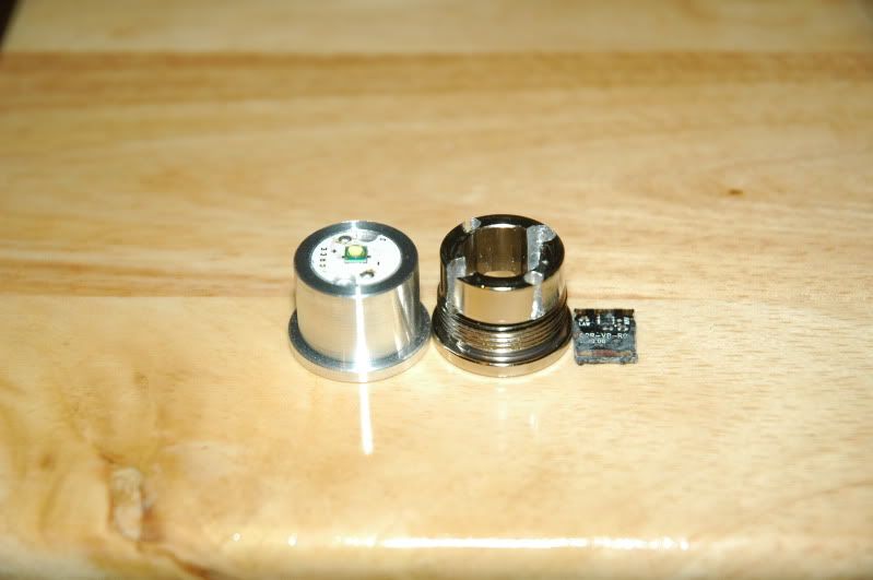
The emitter module is pressed in from the battery side. Some light taps with a rubber mallet onto a flat blade screwdriver with the blade placed beside the emitter (much like you would try to take a Rebel Mini-MagLite apart) will eventually get the module out.


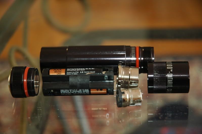
The retaining ring itself is screwed into the body of the light from the battery compartment side. The tools required to take these apart are a strap wrench and a long 12mm Allen wrench. The slots that you are engaging are tapered, starting at about 12.5mm at the battery side and about 11.5mm at the lens side.

DSC_1767.jpg

DSC_1771.jpg


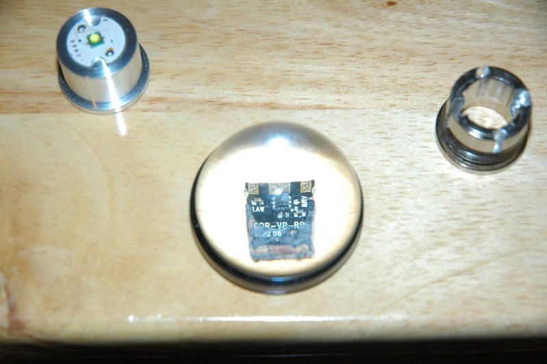
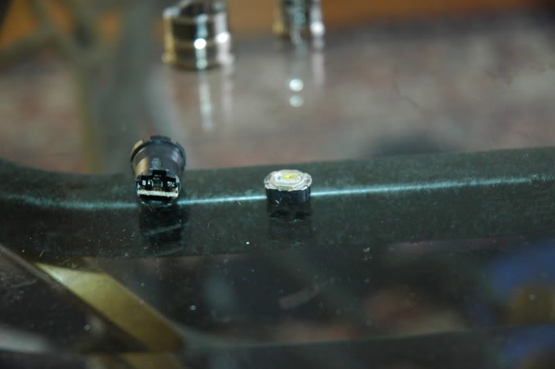
The module itself looks almost like the same modules that Mag uses in their Rebel LED lights but I'm pretty sure that the board on this one is different. Apparently, the tailcap of the XL100 controls the negative current to the emitter to control the modes so I thought that the emitter module might simply be an LED without any circuitry but there is a resistor and a small chip on the board. I haven't taken the board out of its plastic holder, yet, because they glued it into place.

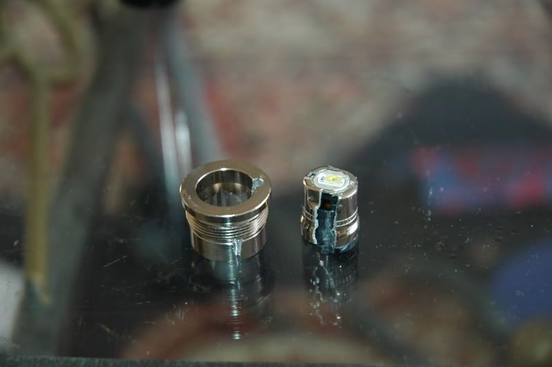
The module itself was something that I wanted to take apart, too, so I took this one apart since I had cut the cannister while trying to remove the retaining ring and I accidentally knocked the dome of the Rebel emitter off during deconstruction. It looks to me like there is a small circuit board sandwiched between a thin metal ring on top and the plastic piece with the contacts on the bottom. I'm going to guess that the glued it together. This sandwich is then glied to the can, exposing only the very top of the sandwich.
DSC_1773.jpg


As a likely mod candidate I would not use this light. The gee-whiz UI is pretty cool but the fact is that it will take a lot of effort to do anything with this light as a host. I do not know if the tailcap will work with a Sandwich Shop driver nor do I think that direct-driving an LED using only the tailcap current to drive it would work well. I have to try it, though.
 

JNewell

Flashlight Enthusiast
Joined
Apr 28, 2006
Messages
1,800
Location
Land of the Bean and the Cod
Nice work and useful post.

Frankly, I think 80% or so of the light is really just a demonstration/feasibility project. However, it's really good to see MagLite doing some genuine innovation, even if it's not all that useful in practical terms. And, it is very good to see an American manufacturer innovating with American-made products. The whiners are totally missing the significance of this.

I do think having a light that will do a low-low-low and has a lockout for travel is useful. It's not perfect, but it's a great step.
 

PCC

Flashlight Enthusiast
Joined
Oct 28, 2007
Messages
2,326
Location
Sitting' on the dock o' The Bay...
I agree that MagLite has finally come out with something that is unique in the market and not a simple MagLite or Mini-MagLite. It would also appear that they designed this light with the intent to have it really difficult to modify unlike the rest of their product line.

WRT to this particular light I plan on making a heatsink to replace the collar and extracting the driver board from the module and integrating that with an XP-G for more output (my son likes them bright).
 

elumen8

Enlightened
Joined
May 19, 2008
Messages
271
Location
San Jose, California
Yeah, I think I voided the warranty on this one. I think my son will be upset with me, too, since this was his light (I'll buy him a new one).

Thanks for taking one for the team and disecting the light. Was it difficult to remove the retaining ring? Now that I see how the retaining ring can removed, I've got some ideas for a mod.

I wired a P60L to the positive and negative leads on the front of the battery carrier and it lit up and retained all the modes (not at full power of course.) I think someone will figure out a way to mod this thing someday.

JB

btw...I have five XLs now, two of which are blue.
 

PCC

Flashlight Enthusiast
Joined
Oct 28, 2007
Messages
2,326
Location
Sitting' on the dock o' The Bay...
Jamie, I used a strap wrench to hold the body still while torquing on the tool to loosen the retaining ring to get it out.

It's interesting that the module assembly lights a P60L. I would love to run this setup with something like a Sandwich Shop Mad Max Lite or Max.
 

PCC

Flashlight Enthusiast
Joined
Oct 28, 2007
Messages
2,326
Location
Sitting' on the dock o' The Bay...
Today, I made a heatsink for this light.

DSC_1776.jpg


MAJOR FAIL!!!. I cut the recess in the face of it too deep and the overall result is that the LED is sitting very deep under the reflector. Not good. I'll make another one tomorrow or during the week as time permits. The idea is to AA the heatsink into the body tube of the light. Right now the narrower section is an almost friction fit inside the body tube so I'll have to have it a touch larger on my next try.

Oh, BTW, I removed the original driver from the module and here's a picture of it. I can get a better picture of it if I break out the macro gear but I figured that a quick picture of it would be better than nothing.

DSC_1781.jpg
 

elumen8

Enlightened
Joined
May 19, 2008
Messages
271
Location
San Jose, California
Holy $h?t that was fast...I wanna come over to your house and play.

How did you turn the heatsink? Are you using the Max? How much will that setup draw? Questions questions...

Jamie
 

PCC

Flashlight Enthusiast
Joined
Oct 28, 2007
Messages
2,326
Location
Sitting' on the dock o' The Bay...
Actually, it's not anywhere close to done. The heatsink is just a slug of aluminum that I cut the other day. I have a Sherline Miniature mill in the garage and, with a 4-jaw chuck and some creative use of a vise attached to a rotary table, use it as a lathe. The XP-G R5 is just sitting in the recess that I cut into the face of it. At this point I'm thinking of just using the original board that came with the XL100, figuring that the more efficient XP-G will give it a 30% boost in output. I need to place an order with the SS to get some drivers to try with this setup but so far money has been really tight and getting tighter. As mentioned in the first post of this thread, I need some (cheap) distractions from things going on in my life right now so I threw this little project together. I hope to get it done in the next week or so.
 

elumen8

Enlightened
Joined
May 19, 2008
Messages
271
Location
San Jose, California
Great work, can't wait to see it finished . Depending on how well this build goes, you might be able to turn down the heatsink to fit the other lights in the MagLED line-up (2AA, 2D, 3D).

Jamie
 

PCC

Flashlight Enthusiast
Joined
Oct 28, 2007
Messages
2,326
Location
Sitting' on the dock o' The Bay...
I'm ahead of you on this one, Jamie. It's actually simpler (IMO) to make a heatsink for the newer Rebel Mini-MagLED than for the older one. WRT to the larger 2D and 3D MagLEDs a more traditional heatsink would probably work better, especially for heat dissipation.
 

PCC

Flashlight Enthusiast
Joined
Oct 28, 2007
Messages
2,326
Location
Sitting' on the dock o' The Bay...
You know, Craig, I had no intention of making this a progress thread when I posted this originally, but it's turning out to be. Maybe down the road I'll spice this light up a bit with a nicer driver or something.
 

elumen8

Enlightened
Joined
May 19, 2008
Messages
271
Location
San Jose, California
Just thought I'd pass along my 'what an idiot move'...I was playing with the battery holder and tailcap, connecting the output to various LED modules, when I accidently reversed the polarity connections on the tailcap. Needles to say, I FRIED the tailcap UI circuitry. If I can't get it to work again, I'll tear apart the tailcap and post pictures. Good times.

JB
 

swampgator

Enlightened
Joined
Aug 29, 2006
Messages
777
Location
Gatorville, Florida
JNewell;3423423[b said:
However, it's really good to see MagLite doing some genuine innovation, even if it's not all that useful in practical terms. And, it is very good to see an American manufacturer innovating with American-made products. The whiners are totally missing the significance of this.[/b]

I own about 25 or so Mags in various configurations, so I know I'm not a Mag basher. However until very recently Mag, IMO, has been resting on its laurels. I am glad to see Mag do something innovative again!

I'll probably pick one of these up pretty soon. I haven't delved into the realm of LEDs so far, but this looks interesting enough. I'm really interested on the new 2C's coming out soon.
 
Last edited:

PCC

Flashlight Enthusiast
Joined
Oct 28, 2007
Messages
2,326
Location
Sitting' on the dock o' The Bay...
Just thought I'd pass along my 'what an idiot move'...I was playing with the battery holder and tailcap, connecting the output to various LED modules, when I accidently reversed the polarity connections on the tailcap. Needles to say, I FRIED the tailcap UI circuitry. If I can't get it to work again, I'll tear apart the tailcap and post pictures. Good times.

JB
Jamie, did you ever take that tailcap apart?

I tried something interesting today: I put the LED module from a 3D Rebel Mag into the XL100 and it was considerably dimmer. The low setting is estimated to be around .5 or 1 lumens. My Quark MiNi 123 puts out 3 lumens on low and it blows the XL100 with 3D module away. On its highest setting it's somewhere around 25 lumens. That same module pulled about 700mA from 3 fresh D cells before I put it into the XL100. Now I'm curious how the original XL100 module would work in my 2D or 3D MagLED? Too bad I ripped that module apart. I can try putting the board into my 2D module and see how it works. More info tomorrow.
 

elumen8

Enlightened
Joined
May 19, 2008
Messages
271
Location
San Jose, California
Jamie, did you ever take that tailcap apart?

I tried something interesting today: I put the LED module from a 3D Rebel Mag into the XL100 and it was considerably dimmer. The low setting is estimated to be around .5 or 1 lumens. My Quark MiNi 123 puts out 3 lumens on low and it blows the XL100 with 3D module away. On its highest setting it's somewhere around 25 lumens. That same module pulled about 700mA from 3 fresh D cells before I put it into the XL100. Now I'm curious how the original XL100 module would work in my 2D or 3D MagLED? Too bad I ripped that module apart. I can try putting the board into my 2D module and see how it works. More info tomorrow.

I haven't pulled the tailcap apart yet, but I will put the XL100 pill into one of my 3D MagLEDs and see what happens.

JB
 

PCC

Flashlight Enthusiast
Joined
Oct 28, 2007
Messages
2,326
Location
Sitting' on the dock o' The Bay...
I'd like to hear the results from that. I would try putting it into a 2D (or 3D with spacer) before putting it into a 3D, just in case it has a boost circuit in it. I can't tell what kind of circuit it has but it makes sense that it would have a boost circuit in it since it is now dimmer with the 3D module.
 

PCC

Flashlight Enthusiast
Joined
Oct 28, 2007
Messages
2,326
Location
Sitting' on the dock o' The Bay...
Okay, now I'm confused. I put the XL-100 circuit board into the capsule that I took out of my 2D MagLED and put that into my 2D Mag and it was dim. I then put it into my 3D Mag and it was just as dim on 3D cells It drew about 560mA in that config while the 3D module pulled a bit more than 700mA. I put the module with the XL-100 circuit board into the XL-100 and it was dim, just like it was with the 3D module. The XL-100 and the 3D MagLED do not use the same circuit board. The XL-100 board is a really simple, one-sided affair with one chip and a few SMD resistors on it while the 3D module looks like it has a bunch of circuitry on it, much like the 2D module. Oh, yeah, the 3D module is potted into the positive contact like the XL-100 board was. My older 2D Rebel MagLED is not potted so I can take out the circuit board and change it at will.

I'm beginning to think that an XP-G without any circuitry or maybe a low value resistor would work well with this tailcap and battery configuration?
 

PCC

Flashlight Enthusiast
Joined
Oct 28, 2007
Messages
2,326
Location
Sitting' on the dock o' The Bay...
I put the LED module from a 3D Rebel Mag into the XL100 and it was considerably dimmer.
Okay, I figured this one out. Put fresh batteries into the light and, wa-la, brighter light :fail:

The XL-100 seems to be no brighter with the 2D nor the 3D module compared to the original module, or at least the 2D module with the XL-100 circuit board. The real surprise was the 2D module: it was only slightly brighter than the other two modules, maybe the same as the 3D module which might be a hair brighter than the XL-100 module. I can't really tell and it takes a minute or two to change modules/circuit boards. Nope, I don't have a meter to measure any difference. This does tell me, though, that the tailcap probably has current limiting circuitry as the 2D module would normally pull 1600+ mA from 2.4V and is pretty bright compared to the XL-100 in a 2D Mag.

I'm still thinking of using the original board in that heatsink I made before with an XP-G on a thicker 10mm board. I just need to order the emitter.
 

Latest posts

Top