
wquiles
Flashaholic
Forum member mdocod (Eric) and I have been working for a while now developing a custom "pack" for the SureFire M6 flashlight, which I call the PhD-M6 (programmable hotwire driver for the M6).
The PhD-M6 pack consists of a custom battery carrier by Eric, and a custom, microprocessor controller driver running on a custom PWB designed, and programmed by me. Eric sends me the custom battery carrier, and I assemble, program, calibrate, and test each pack, which I then send to each buyer (domestic or international). The only thing you will need will be to provide your own M6 and your own 17670 batteries/charger.
Note that the PhD-M6 pack is of a "buck" type voltage regulator. The loaded battery voltage needs to be higher than the target RMS voltage for the pack to be able to regulate the output. The micro-controller does this true voltage regulation by implementing a close feedback loop in which the micro-controller is constantly monitoring the voltage under load of the cells, and then adjusting (increasing) the duty cycle to compensate as the batteries drain. As the batteries drain, the duty cycle of the PWM signal will increase to its max., but past that point, the regulator can no longer maintain the target output voltage, so the RMS output will keep dropping and the bulb will start to dim, until the cells are depleted (the built-in protection on the cells is reached). Since the switching element (MOSFET) is either ON or OFF, and since it only has approximately 6mOhms (0.006 Ohms) when it is ON, even at 5 amps you only have a drop across the FET of less than 50mili Volts, so this regulator offers extremely high efficiency (95-99% efficiency).
The development and testing of the pack is described in detail in this thread:
The PhD-M6 thread (programmable hotwire driver for the SF-M6) ...
Reference material on the PWM regulation scheme originated with forum member Alan B in this thread. Kudos to him for getting this started which then allowed me to work on this variant for the M6.
Currently the PhD-M6 pack has the following features:
- Uses PWM (pulse width modulation) to offer true voltage regulation for incandescent bulbs
- Soft start via PWM, while allowing for fast ON/OFF operation (for example while signaling).
- Runs from 3x 17670 AW (black label) protected cells
- The PhD-M6 pack incorporates low voltage detection (while the cells are loaded, for more accurate results)
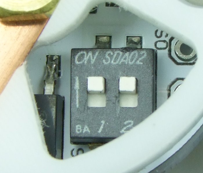
- Four (4) user-selectable output voltage, via integrated surface mount 2-position DIP switch
NOTE: This pack does not require any alteration to the M6. It is literally a drop-in pack. All you do is insert batteries into the side-loading pack, select the voltage/bulb in the two dip switches, put the corresponding bulb in the head of the M6, and go
To operate the pack:
1) Insert the desired bulb in the M6
2) Insert protected 17670 cells into the PhD-M6 pack.
NOTE the polarity of the cells. The pack might be damaged if the cells are installed backwards!
3) Out of the 4 possible voltage selections, pick the one that best matches the bulb used in step 1. Set the two switches as follows:
Level 1 - Target Voltage = 5.0 volts
For use with the SureFire N1. WA1218 might also work with a bi-pin adapter (maybe). A SureFire Z46 (M3 head) modded to accept D36 lamps could possibly be used to run Wolf-Eyes and Pila "6V" D36 incandecent lamps.
Switch position: OFF OFF

Level 2 - Target Voltage = 6.8 volts
For use with the SureFire MN16 and MN21 primarily. MN11 can be used in a Z46 head. WA1160 w/FM bi-pin adapter.
Switch position: OFF ON
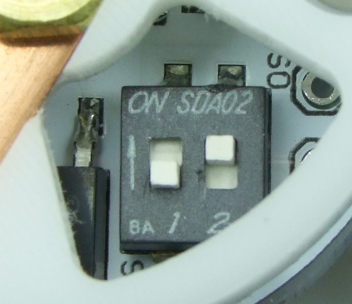
Level 3 - Target Voltage = 7.5 volts
For use with SureFire MN15, N2, MN20, N62 in stock TurboHead. SureFire MN10, LumensFactory HO-M3, EO-M3 and IMR-M3 in SF Z46 head. All "9V" style D36 lamps in a modded Z46 head (Wolf-Eyes, Pila 9V D36 lamps, LF SR-9L, HO-9L, EO-9L, IMR-9L). Osram 64250, Carley 1057, MagCharger bulb (GE 787), and possibly other bi-pin lamps in an FM bi-pin adapter.
Switch position: ON OFF
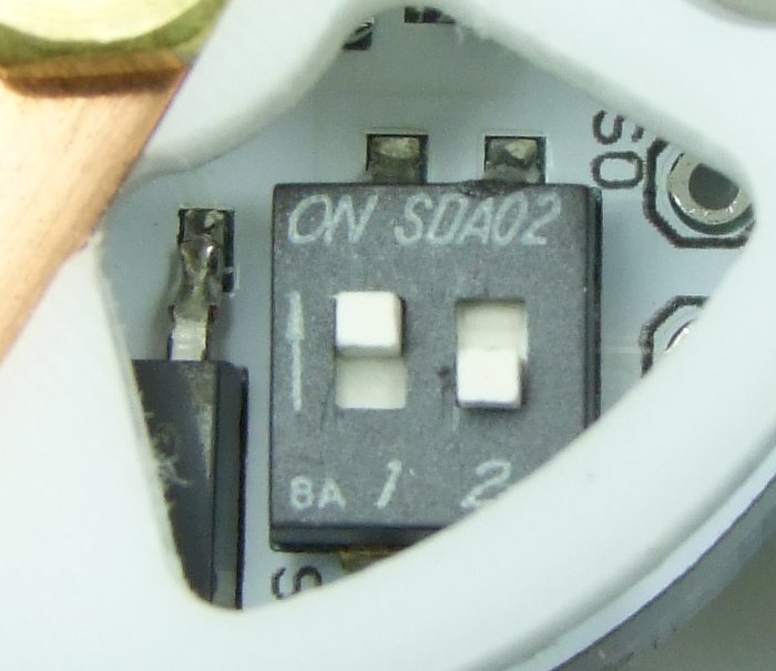
Level 4 - Target Voltage = 10.8
For use with the WA1185, IMR-M6 and HO-M6R bulbs. Could also be used with the SureFire MN60 and get some pretty good over-drive. The MN61 would be over-driven so heavily I would not expect it to last long at all but it might work for some. LumensFactory HO-13, EO-13, and IMR-13 D36 lamps could all be used in a modded Z46 head.
Switch position: ON ON
The bulb does not have a POS or NEG terminal, so the pack can be inserted either way into the M6. However, due to the close tolerances in the pack to maximize space for the board, it is much easier and convenient to put the pack into the M6 with the circuit board towards the tailcap, as shown here. This of course makes it very easy to also change the voltage setting for the bulb without having to remove the pack from the M6 (the white plastic "thing" at the bottom is a safety small kid cover for the power outlets in my home):

*****************************************
Videos: Here are some videos of the driver doing the voltage regulation, soft-start, low voltage operation, etc.:
PhD-M6 Video 1 - Target Voltage = 10.8 Vrms
- Shows PWM at max. since supply voltage is not high enough. As the voltage is then increased, the PWM then adapts to the higher voltage. Note that the bulb voltage is finally what needs to be for this setting (10.8V).
http://www.youtube.com/watch?v=RUBoduybtkw
PhD-M6 Video 2 - Target Voltage = 4.8 Vrms
- Here the power supply's voltage is high enough to give the 4.8V to the bulb. As I increase/decrease the supply's voltage, you can see how the PWM duty cycle adapts accordingly (duty cycle gets longer when the voltage is lower).
http://www.youtube.com/watch?v=j_irprTBPFs
PhD-M6 Video 3 - Bulb detection and soft start in action - Target voltage = 4.8Vrms
- This is not the final configuration for bulb detection, but in this video, when both traces show the nice square-looking waves, that means there is a bulb connected. Also, as the bulb is connected, you can see the brief build of the PWM modulation when doing the soft start.
http://www.youtube.com/watch?v=CLUU1wyXTt4
PhD-M6 Video 4 - Bulb soft start in action - Target voltage = 4.8Vrms
- In here you can barely see the soft start in action for the target voltage of 4.8V.
http://www.youtube.com/watch?v=x1l21FjuBS4
PhD-M6 Video 5 - Bulb soft start in action - Target voltage = 10.8Vrms
- Bulb soft start done twice, both times for target voltage 10.8V. First time the power supply is set too low, so the PWM goes to max value but can't give the bulb full voltage since power supply is too low. Second time I adjusted the power supply to provide plenty of voltage, so you can more clearly see the soft start in action.
http://www.youtube.com/watch?v=sFlaCeoRlw8
PhD-M6 Video 6 - Low Voltage and Shutdown Operation - Target voltage = 10.8Vrms
A few things to note about the current operation of the PhD-M6:
1) The pack has been designed to work ONLY with protected 17670 cells, preferably the black label AW protected cells. We are getting about an hour of runtime with the MN20 and about 25 minutes with the MN21 bulb.
2) Operation with the older AW blue label protected cells has been verified at lower currents (MN20), but at the larger loads (like with the MN21 and others), the protection circuitry in those cells can't handle the high current load and the cells shutdown early (before they are depleted).
3) The pack will shutdown then the cells' built-in protection is triggered, so again, you MUST use protected cells with this pack. I do (at least for the moment) have a very low voltage shutdown setpoint at about 7.5 volts, so if the loaded voltage for the pack (3x 17670) gets that low, the pack will shutdown to protect the cells. This sets a persistent flag. Turning ON/OFF the light will not clear this flag. You have to remove the batteries (well, at least one cell) to force a reset which will then clear this flag.
4) Removing and reinstalling the batteries from the pack always forces a full reset.
5) As soon as you put batteries in the PhD-M6 pack, the pack goes into sleep mode right away, drawing very, very little current (less than 1mA - in fact in one of my power supplies the current meter goes to zero since it can't measure that low!). The pack will come out of sleep as soon as it detects the bulb is now connected, which happens when you close the tailcap or press the switch to close the circuit and turn the M6 ON.
6) To change the voltage setting you can remove the batteries if you want, but don't have to remove the batteries from the pack. Just remove the pack from the light, select the new voltage setting via the dip switches, change the bulb in the head, and re-insert the pack into the M6. As soon as you close the tailcap/press the button, the PhD-M6 pack comes out of sleep mode and reads the switch position before starting regulation.
7) This regulator/driver will NOT work with LED's. It is designed only to work with incandescent bulbs.
*****************************************
Fast ON/OFF (signaling operation):
One of the things I wanted to make sure works flawlessly is the ability of the M6 to work not only in momentary mode, but also in fast signaling mode - turning ON/OFF as quickly as humanly possible. This is one of the several tests I have done to verify the PhD-M6 works as intended, this time with the MN15 being driven at 7.4Vrms.
PhD-M6 Video 7 - Quick On/Off behavior testing - MN15 (7.4Vrms)
You can also of course see the soft-start in action as well. Kind of cool to see a 7.4Vrms bulb being driven from a 12Volt power supply, isn't? :devil:
*****************************************
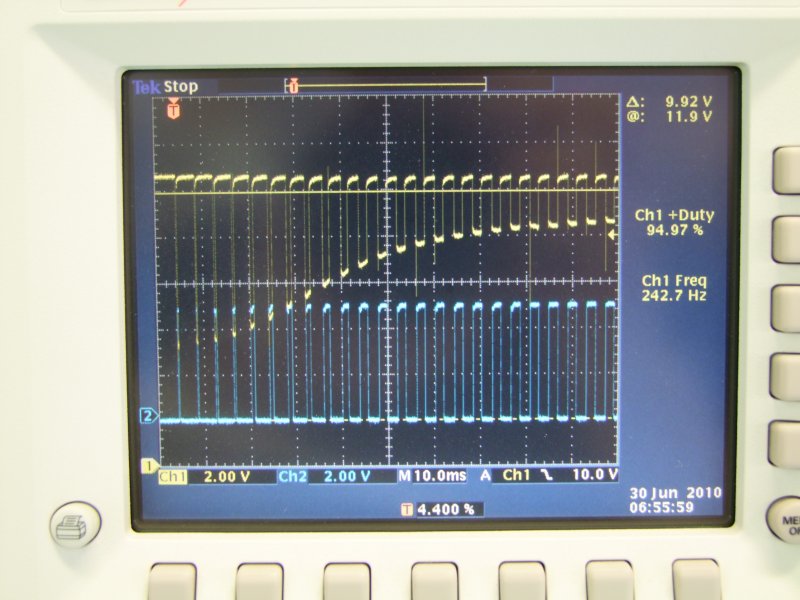
First photo is with a low power 12V bulb being driven at 10.8 volts (level 4). Yellow trace is at the battery, and the blue trace is at the gate of the FET. Here you can see several things:
1) Note soft-start taking place. Note how the width of the blue trace starts very, very narrow, and slowly gets wider and wider as time pases on (10mS per division). Roughly after 100mS or so the regulator achieves steady state.
2) Note that at the very beginning, when the bulb is "cold" (and its resistance the lowest) that the voltage sag on the cells/batteries is largest, but as the bulb warms up the voltage sag is less and less, as the resistance in the bulb increases.
3) Note that the FET (blue trace) is basically either ON or OFF. When the signal at the gate is high, the FET turns ON, when the signal at the gate goes to zero, the FET turns OFF. Note the battery voltage only sags while the FET is ON. This is the period of time where the regulator is measuring the battery voltage to adjust regulation.
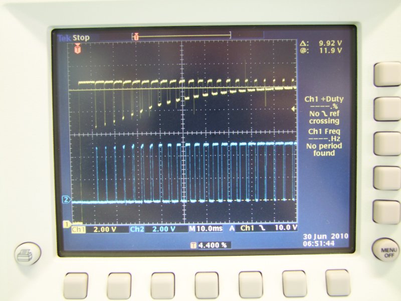
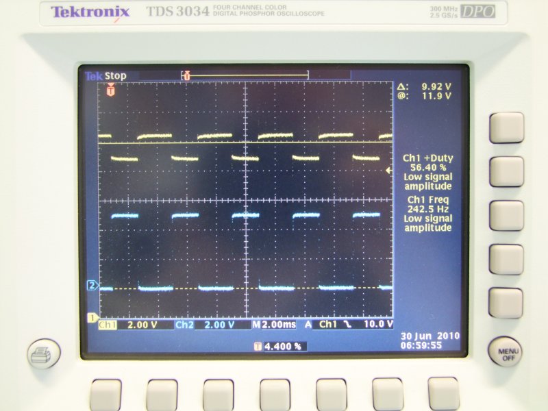
In this second shot, I am doing the same exact thing as above, but this time with a SF MN20 bulb being driven at its target 7.8 volts (level 3). Again, in approx. 100mS the output is now stable. Note that since the target voltage is lower, the duty cycle is less than on the scope photo above where the duty cycle is pretty high:
This scope shot is of the steady state with the MN20 - once the soft start part has ended, and the voltage regulation is taking place (again top yellow trace is the battery, lower blue trace if the gate signal for the FET):
*********************************************************************************
*********************************************************************************
*********************************************************************************
Price and availability:
I have finalized pricing for the completed PhD-M6 pack, and when I open the formal sales thread, this is the pricing that will be used:
- Regular price for CPF members: $195
- Regular price for non-CPF members: $245
- Custom programming values: $20 at the initial time of sale. Charge will be $40 (plus shipping) if I have to reprogram a pack already sold.
- Forum member is defined as being a member of the forum before the feeler thread started (June 29, 2010).
However, in order to do say thanks to the folks who have contributed so much to this feeler thread and expressed their interest to buy one, I will be offering the PhD-M6 pack at the special introductory price of $145, for those 38 forum members that expressed their interest in the feeler thread (42 packs max as of the end of July). As I mentioned earlier, that was a non-committal list, so those 38 forum members don't have to buy a pack, but if they do want one, those forum members can buy it at the special introductory price.
Prices don't include shipping, insurance, nor tracking, and you need to provide your own 3x protected 17670 cells/charger. I will clarify shipping options on the sale thread, but I am expecting to use USPS Priority Shipping Small Flat Rate box which will be $5 domestic (USA) and $15 for international destinations.
Eric and I have already been ordering parts and building production pieces based on these feeler quantities (and some extra amount), so as soon as we get feedback from LuxLuthor and leukos, and assuming that they determine the pack is ready, I will start the sales thread.
__________________
Before I go much further I want to thank Alan, Jimmy, George, Eric and others for helping me get this project moving - they truly have been awesome and have taught me a lot :bow:
Will
The PhD-M6 pack consists of a custom battery carrier by Eric, and a custom, microprocessor controller driver running on a custom PWB designed, and programmed by me. Eric sends me the custom battery carrier, and I assemble, program, calibrate, and test each pack, which I then send to each buyer (domestic or international). The only thing you will need will be to provide your own M6 and your own 17670 batteries/charger.
Note that the PhD-M6 pack is of a "buck" type voltage regulator. The loaded battery voltage needs to be higher than the target RMS voltage for the pack to be able to regulate the output. The micro-controller does this true voltage regulation by implementing a close feedback loop in which the micro-controller is constantly monitoring the voltage under load of the cells, and then adjusting (increasing) the duty cycle to compensate as the batteries drain. As the batteries drain, the duty cycle of the PWM signal will increase to its max., but past that point, the regulator can no longer maintain the target output voltage, so the RMS output will keep dropping and the bulb will start to dim, until the cells are depleted (the built-in protection on the cells is reached). Since the switching element (MOSFET) is either ON or OFF, and since it only has approximately 6mOhms (0.006 Ohms) when it is ON, even at 5 amps you only have a drop across the FET of less than 50mili Volts, so this regulator offers extremely high efficiency (95-99% efficiency).
The development and testing of the pack is described in detail in this thread:
The PhD-M6 thread (programmable hotwire driver for the SF-M6) ...
Reference material on the PWM regulation scheme originated with forum member Alan B in this thread. Kudos to him for getting this started which then allowed me to work on this variant for the M6.
Currently the PhD-M6 pack has the following features:
- Uses PWM (pulse width modulation) to offer true voltage regulation for incandescent bulbs
- Soft start via PWM, while allowing for fast ON/OFF operation (for example while signaling).
- Runs from 3x 17670 AW (black label) protected cells
- The PhD-M6 pack incorporates low voltage detection (while the cells are loaded, for more accurate results)
- Four (4) user-selectable output voltage, via integrated surface mount 2-position DIP switch
NOTE: This pack does not require any alteration to the M6. It is literally a drop-in pack. All you do is insert batteries into the side-loading pack, select the voltage/bulb in the two dip switches, put the corresponding bulb in the head of the M6, and go
To operate the pack:
1) Insert the desired bulb in the M6
2) Insert protected 17670 cells into the PhD-M6 pack.
NOTE the polarity of the cells. The pack might be damaged if the cells are installed backwards!
3) Out of the 4 possible voltage selections, pick the one that best matches the bulb used in step 1. Set the two switches as follows:
Level 1 - Target Voltage = 5.0 volts
For use with the SureFire N1. WA1218 might also work with a bi-pin adapter (maybe). A SureFire Z46 (M3 head) modded to accept D36 lamps could possibly be used to run Wolf-Eyes and Pila "6V" D36 incandecent lamps.
Switch position: OFF OFF
Level 2 - Target Voltage = 6.8 volts
For use with the SureFire MN16 and MN21 primarily. MN11 can be used in a Z46 head. WA1160 w/FM bi-pin adapter.
Switch position: OFF ON
Level 3 - Target Voltage = 7.5 volts
For use with SureFire MN15, N2, MN20, N62 in stock TurboHead. SureFire MN10, LumensFactory HO-M3, EO-M3 and IMR-M3 in SF Z46 head. All "9V" style D36 lamps in a modded Z46 head (Wolf-Eyes, Pila 9V D36 lamps, LF SR-9L, HO-9L, EO-9L, IMR-9L). Osram 64250, Carley 1057, MagCharger bulb (GE 787), and possibly other bi-pin lamps in an FM bi-pin adapter.
Switch position: ON OFF
Level 4 - Target Voltage = 10.8
For use with the WA1185, IMR-M6 and HO-M6R bulbs. Could also be used with the SureFire MN60 and get some pretty good over-drive. The MN61 would be over-driven so heavily I would not expect it to last long at all but it might work for some. LumensFactory HO-13, EO-13, and IMR-13 D36 lamps could all be used in a modded Z46 head.
Switch position: ON ON
The bulb does not have a POS or NEG terminal, so the pack can be inserted either way into the M6. However, due to the close tolerances in the pack to maximize space for the board, it is much easier and convenient to put the pack into the M6 with the circuit board towards the tailcap, as shown here. This of course makes it very easy to also change the voltage setting for the bulb without having to remove the pack from the M6 (the white plastic "thing" at the bottom is a safety small kid cover for the power outlets in my home):
*****************************************
Videos: Here are some videos of the driver doing the voltage regulation, soft-start, low voltage operation, etc.:
PhD-M6 Video 1 - Target Voltage = 10.8 Vrms
- Shows PWM at max. since supply voltage is not high enough. As the voltage is then increased, the PWM then adapts to the higher voltage. Note that the bulb voltage is finally what needs to be for this setting (10.8V).
http://www.youtube.com/watch?v=RUBoduybtkw
PhD-M6 Video 2 - Target Voltage = 4.8 Vrms
- Here the power supply's voltage is high enough to give the 4.8V to the bulb. As I increase/decrease the supply's voltage, you can see how the PWM duty cycle adapts accordingly (duty cycle gets longer when the voltage is lower).
http://www.youtube.com/watch?v=j_irprTBPFs
PhD-M6 Video 3 - Bulb detection and soft start in action - Target voltage = 4.8Vrms
- This is not the final configuration for bulb detection, but in this video, when both traces show the nice square-looking waves, that means there is a bulb connected. Also, as the bulb is connected, you can see the brief build of the PWM modulation when doing the soft start.
http://www.youtube.com/watch?v=CLUU1wyXTt4
PhD-M6 Video 4 - Bulb soft start in action - Target voltage = 4.8Vrms
- In here you can barely see the soft start in action for the target voltage of 4.8V.
http://www.youtube.com/watch?v=x1l21FjuBS4
PhD-M6 Video 5 - Bulb soft start in action - Target voltage = 10.8Vrms
- Bulb soft start done twice, both times for target voltage 10.8V. First time the power supply is set too low, so the PWM goes to max value but can't give the bulb full voltage since power supply is too low. Second time I adjusted the power supply to provide plenty of voltage, so you can more clearly see the soft start in action.
http://www.youtube.com/watch?v=sFlaCeoRlw8
PhD-M6 Video 6 - Low Voltage and Shutdown Operation - Target voltage = 10.8Vrms
A few things to note about the current operation of the PhD-M6:
1) The pack has been designed to work ONLY with protected 17670 cells, preferably the black label AW protected cells. We are getting about an hour of runtime with the MN20 and about 25 minutes with the MN21 bulb.
2) Operation with the older AW blue label protected cells has been verified at lower currents (MN20), but at the larger loads (like with the MN21 and others), the protection circuitry in those cells can't handle the high current load and the cells shutdown early (before they are depleted).
3) The pack will shutdown then the cells' built-in protection is triggered, so again, you MUST use protected cells with this pack. I do (at least for the moment) have a very low voltage shutdown setpoint at about 7.5 volts, so if the loaded voltage for the pack (3x 17670) gets that low, the pack will shutdown to protect the cells. This sets a persistent flag. Turning ON/OFF the light will not clear this flag. You have to remove the batteries (well, at least one cell) to force a reset which will then clear this flag.
4) Removing and reinstalling the batteries from the pack always forces a full reset.
5) As soon as you put batteries in the PhD-M6 pack, the pack goes into sleep mode right away, drawing very, very little current (less than 1mA - in fact in one of my power supplies the current meter goes to zero since it can't measure that low!). The pack will come out of sleep as soon as it detects the bulb is now connected, which happens when you close the tailcap or press the switch to close the circuit and turn the M6 ON.
6) To change the voltage setting you can remove the batteries if you want, but don't have to remove the batteries from the pack. Just remove the pack from the light, select the new voltage setting via the dip switches, change the bulb in the head, and re-insert the pack into the M6. As soon as you close the tailcap/press the button, the PhD-M6 pack comes out of sleep mode and reads the switch position before starting regulation.
7) This regulator/driver will NOT work with LED's. It is designed only to work with incandescent bulbs.
*****************************************
Fast ON/OFF (signaling operation):
One of the things I wanted to make sure works flawlessly is the ability of the M6 to work not only in momentary mode, but also in fast signaling mode - turning ON/OFF as quickly as humanly possible. This is one of the several tests I have done to verify the PhD-M6 works as intended, this time with the MN15 being driven at 7.4Vrms.
PhD-M6 Video 7 - Quick On/Off behavior testing - MN15 (7.4Vrms)
You can also of course see the soft-start in action as well. Kind of cool to see a 7.4Vrms bulb being driven from a 12Volt power supply, isn't? :devil:
*****************************************
First photo is with a low power 12V bulb being driven at 10.8 volts (level 4). Yellow trace is at the battery, and the blue trace is at the gate of the FET. Here you can see several things:
1) Note soft-start taking place. Note how the width of the blue trace starts very, very narrow, and slowly gets wider and wider as time pases on (10mS per division). Roughly after 100mS or so the regulator achieves steady state.
2) Note that at the very beginning, when the bulb is "cold" (and its resistance the lowest) that the voltage sag on the cells/batteries is largest, but as the bulb warms up the voltage sag is less and less, as the resistance in the bulb increases.
3) Note that the FET (blue trace) is basically either ON or OFF. When the signal at the gate is high, the FET turns ON, when the signal at the gate goes to zero, the FET turns OFF. Note the battery voltage only sags while the FET is ON. This is the period of time where the regulator is measuring the battery voltage to adjust regulation.
In this second shot, I am doing the same exact thing as above, but this time with a SF MN20 bulb being driven at its target 7.8 volts (level 3). Again, in approx. 100mS the output is now stable. Note that since the target voltage is lower, the duty cycle is less than on the scope photo above where the duty cycle is pretty high:
This scope shot is of the steady state with the MN20 - once the soft start part has ended, and the voltage regulation is taking place (again top yellow trace is the battery, lower blue trace if the gate signal for the FET):
*********************************************************************************
*********************************************************************************
*********************************************************************************
Price and availability:
I have finalized pricing for the completed PhD-M6 pack, and when I open the formal sales thread, this is the pricing that will be used:
- Regular price for CPF members: $195
- Regular price for non-CPF members: $245
- Custom programming values: $20 at the initial time of sale. Charge will be $40 (plus shipping) if I have to reprogram a pack already sold.
- Forum member is defined as being a member of the forum before the feeler thread started (June 29, 2010).
However, in order to do say thanks to the folks who have contributed so much to this feeler thread and expressed their interest to buy one, I will be offering the PhD-M6 pack at the special introductory price of $145, for those 38 forum members that expressed their interest in the feeler thread (42 packs max as of the end of July). As I mentioned earlier, that was a non-committal list, so those 38 forum members don't have to buy a pack, but if they do want one, those forum members can buy it at the special introductory price.
Prices don't include shipping, insurance, nor tracking, and you need to provide your own 3x protected 17670 cells/charger. I will clarify shipping options on the sale thread, but I am expecting to use USPS Priority Shipping Small Flat Rate box which will be $5 domestic (USA) and $15 for international destinations.
Eric and I have already been ordering parts and building production pieces based on these feeler quantities (and some extra amount), so as soon as we get feedback from LuxLuthor and leukos, and assuming that they determine the pack is ready, I will start the sales thread.
__________________
Before I go much further I want to thank Alan, Jimmy, George, Eric and others for helping me get this project moving - they truly have been awesome and have taught me a lot :bow:
Will
Last edited: