wquiles
Flashaholic
This is the second Barbolight U9 that I do for the same customer. The first one I finished about 10 months ago:Barbolight U9 with Warm White MC-E and HipCC
But for this one the owner wanted something more, something unique, and he suggested the SST-50. I suggested using the whole body (3x cells) for decent runtimes with the SST-50, but problem was the H6CC driver from George (www.taskled.com) was not yet available (Nov 2009), so this project was on hold for many months waiting on an efficient driver solution that could handle 3x LiIon cells. Once the driver was available, then another challenge was found: there is no way to fit the H6CC in the U9 host - too big for the body, and no room in the head. I suggested making a completely new, larger head from scratch, the owner agreed. But the head needed to have a couple of critical dimensions, so I decided to do the head design in a 3D package. So I bought Alibre Expert software and did the head design in the computer. Once I was happy with the design, I then started making the new head. I told the owner that I have a new Powder Coating system, and he said he would like his new light in Orange, so after many weeks of practicing/learning how to powder coat, I was able to get this light coated properly.
All in all I have been working on this second light for about 11 months, but it is now finished - I hope the owner will be happy with the result
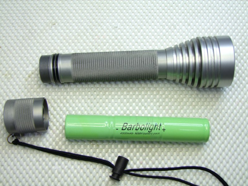
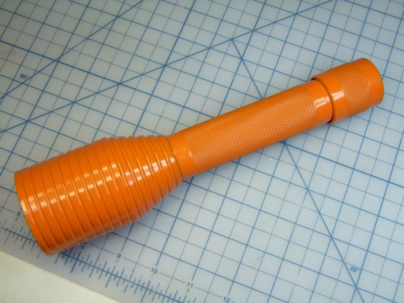
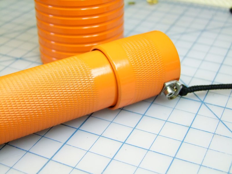
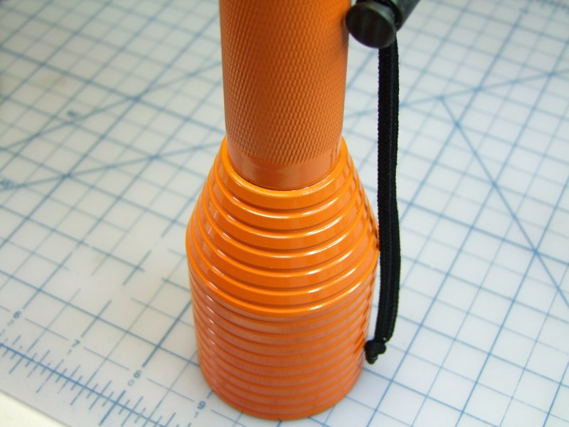
Here is how the light looked like when I got it last year:
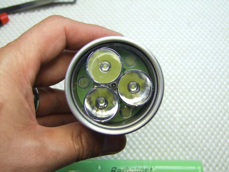
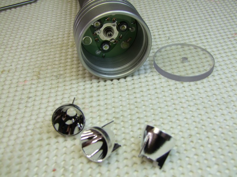
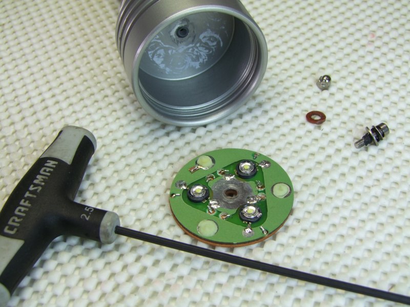
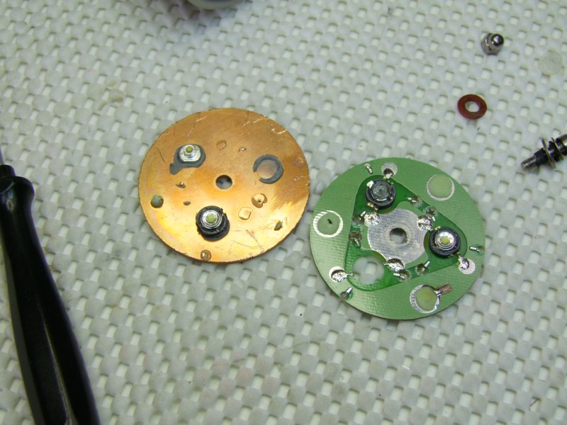
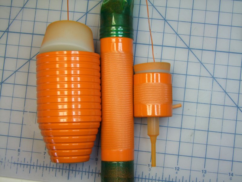
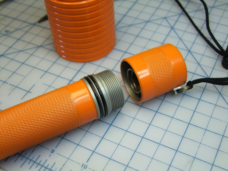
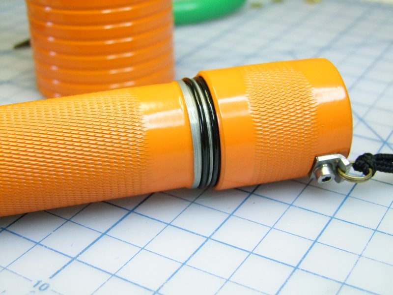
So I started disassembly:
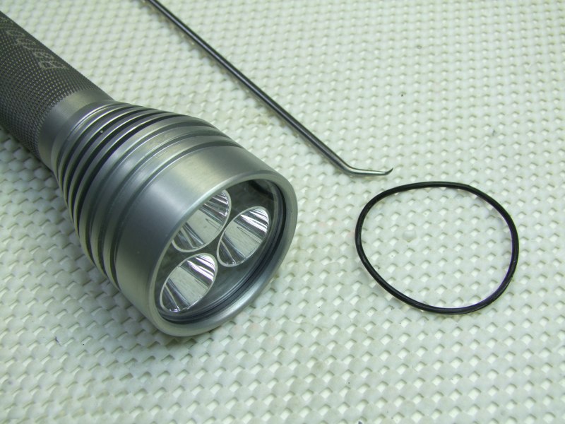
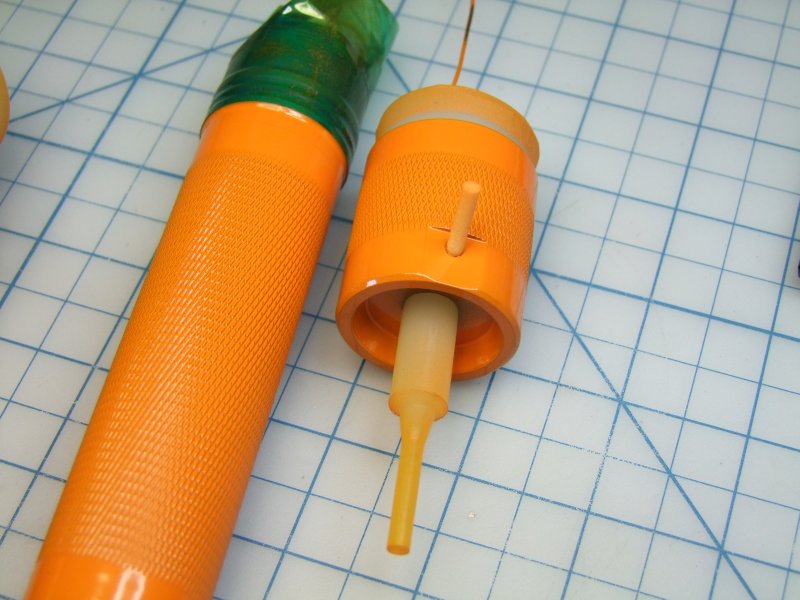
Heating the factory epoxy to remove the head:
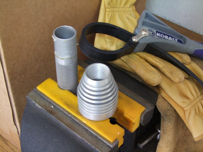
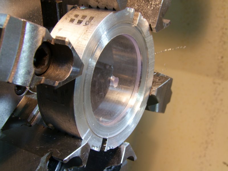
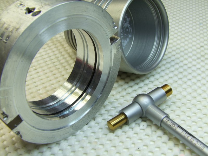
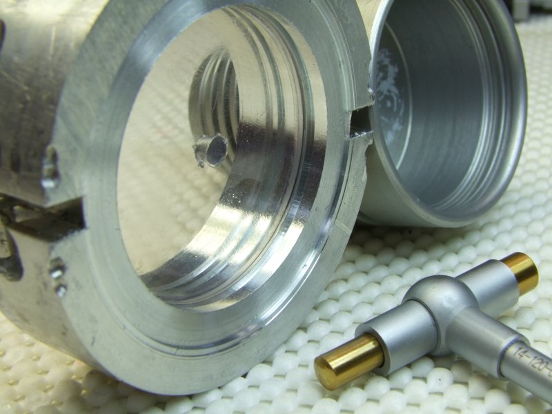
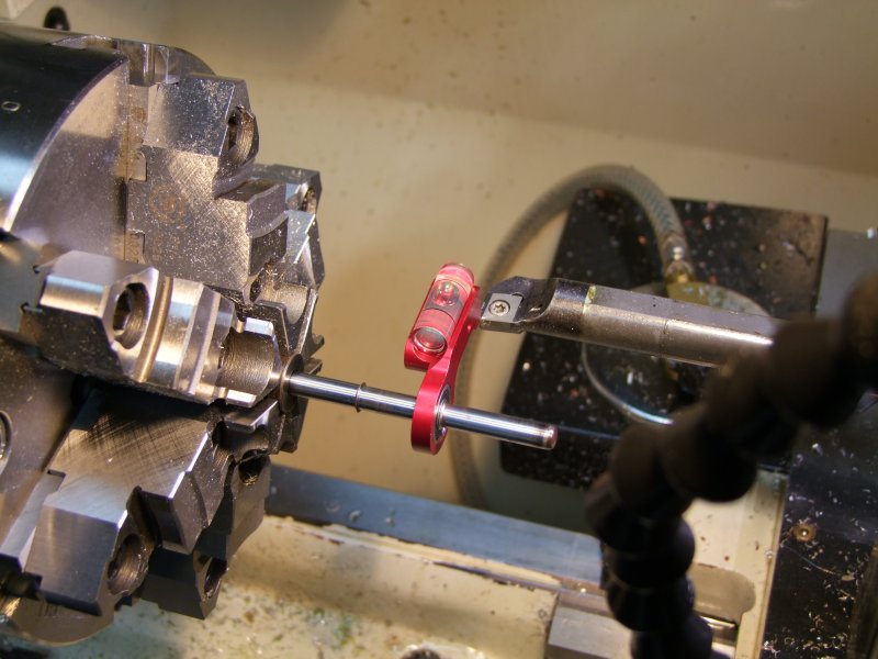
Barbolight uses a proven method for water-proofing the front lens, but it is one of high precision on the o-rings, lens OD, and o-ring groove. Since I have never done this before, I first practiced with a piece of scrap. First got the ID to be a sliding fit with the lens (I also have a spare lens to play with):
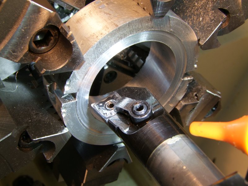
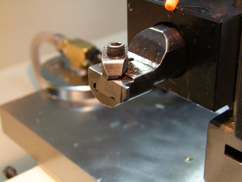
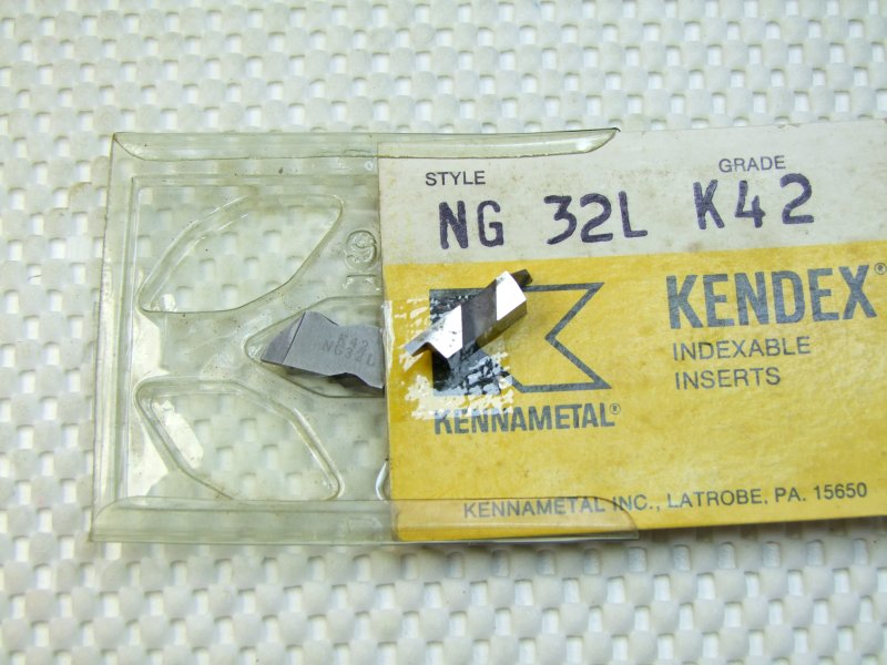
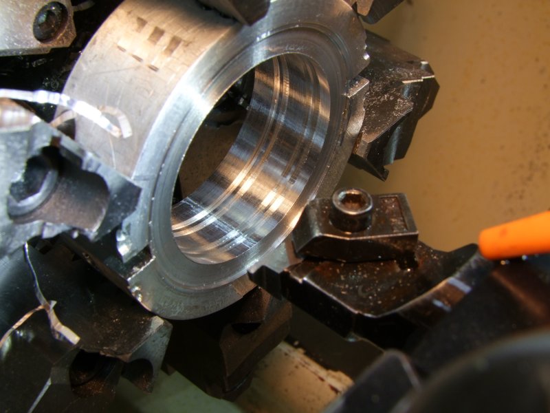
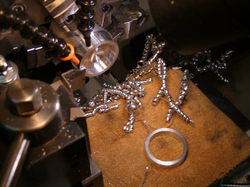
and then cut the o-ring grooves (I did two sets of them):
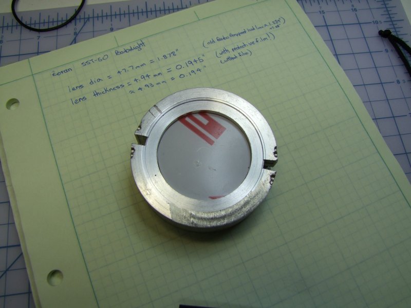
I tested the o-ring and lens (original head to the right side). It works really well:
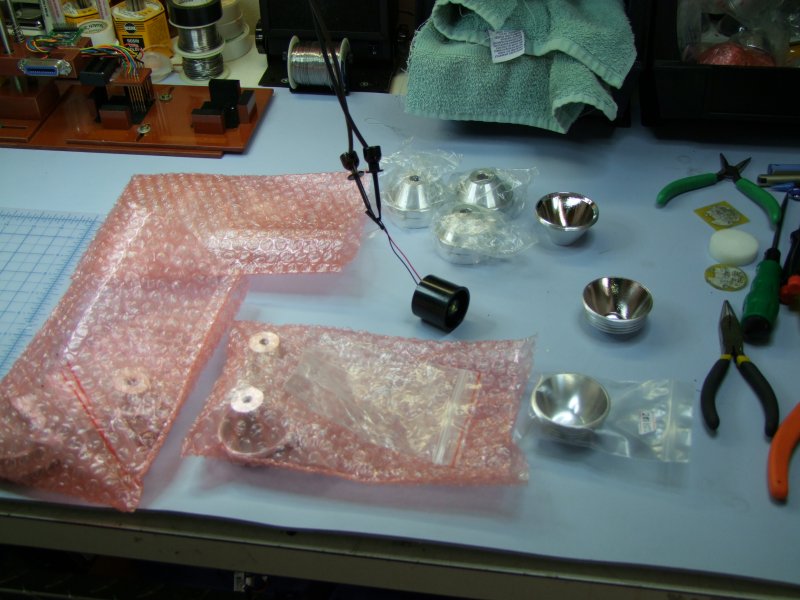
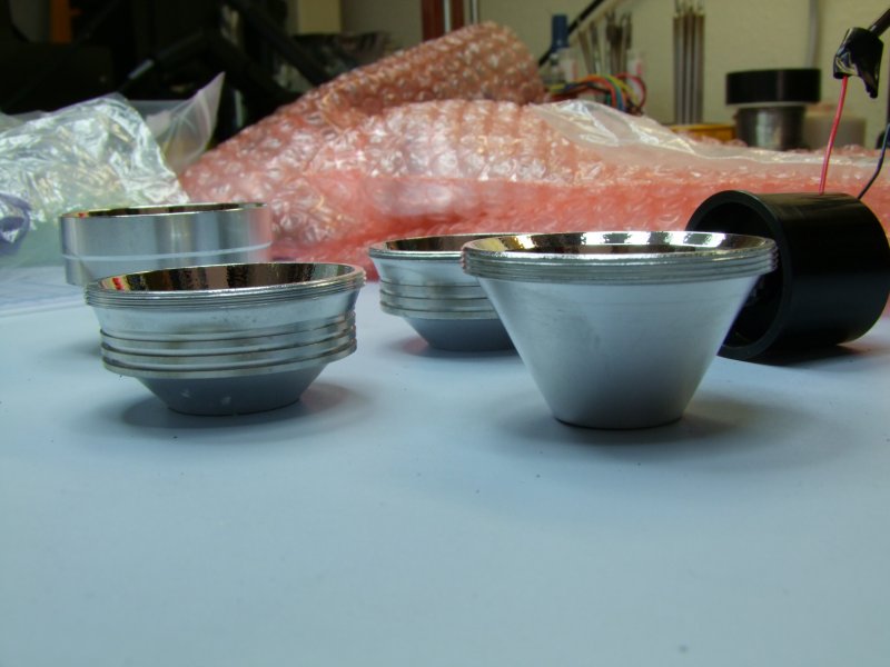
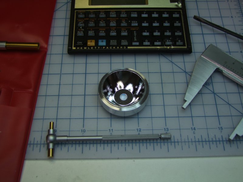
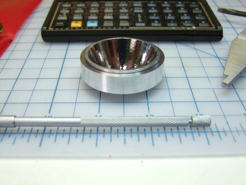
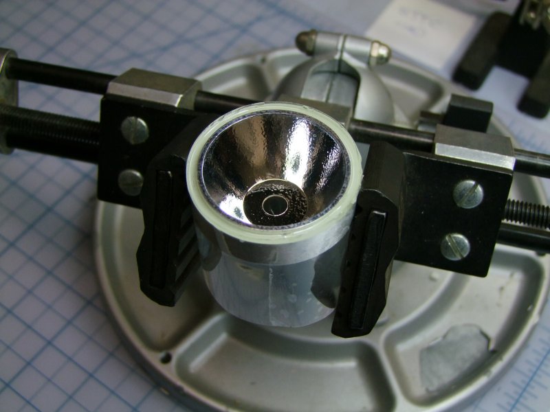
I then played with an SST-50 mounted on a Mag D heatsink with various reflectors. In the end I selected a shallow reflector that worked well, which is the same one I used for the warm MC-E conversion earlier:
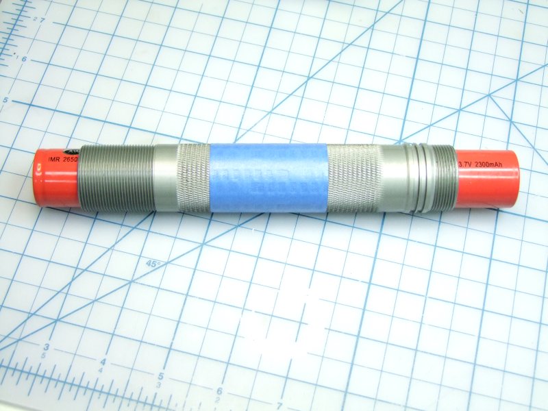
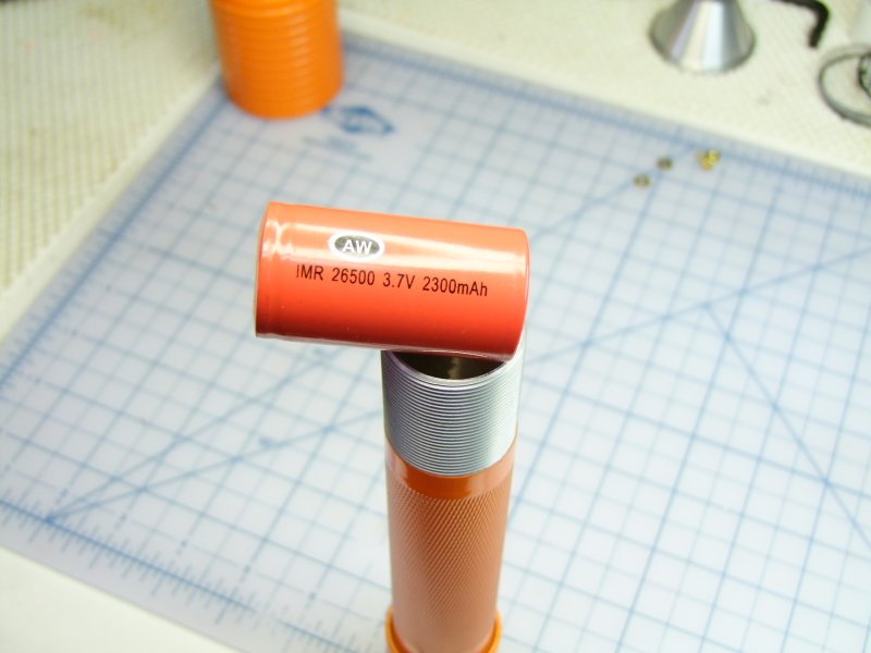
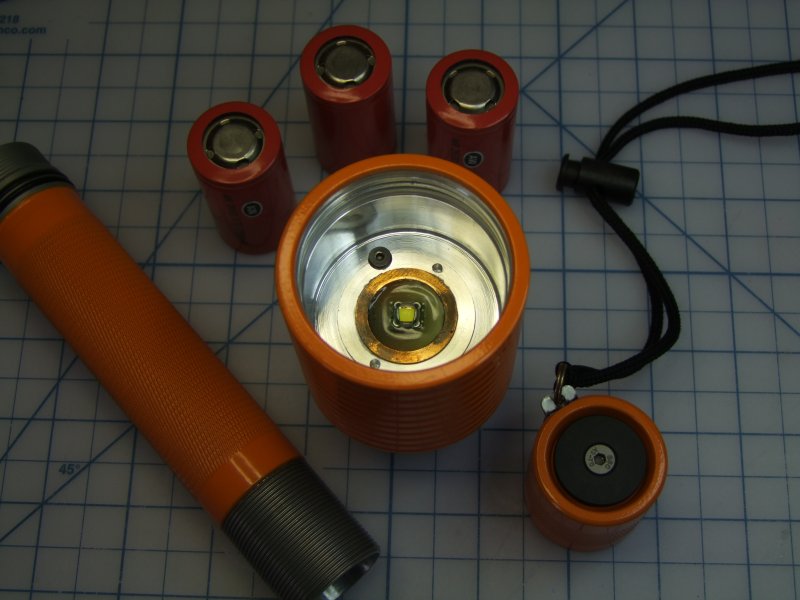
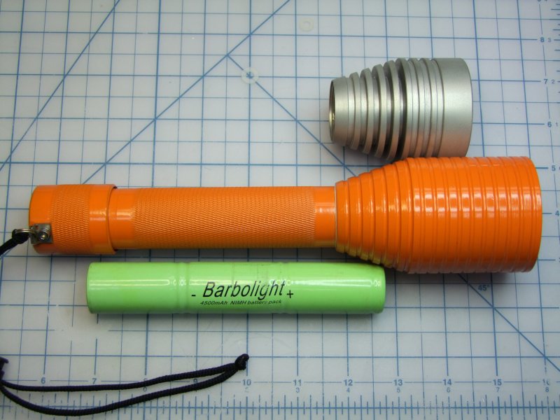
Size comparison of the original host, the original 3x NiMH pack, the will-always-be-missed "C" AW LiIon cells, and the newer but-larger-than-a-true-C-cell IMR:
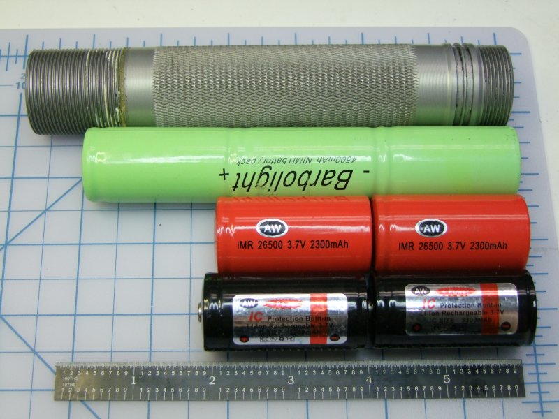
With the tailcap fully inserted, and the spring fully rested, this is how things look like. I did several measurements on the cells, which allowed me keep the original tailcap spring since it meant that I could use either the longer Black/IMR cells since the spring will take up the difference
So the big day arrived when I got the new Al piece for the new head:
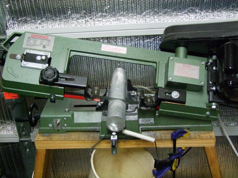
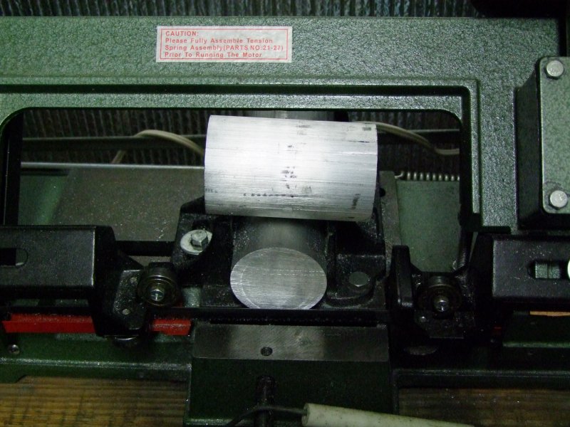
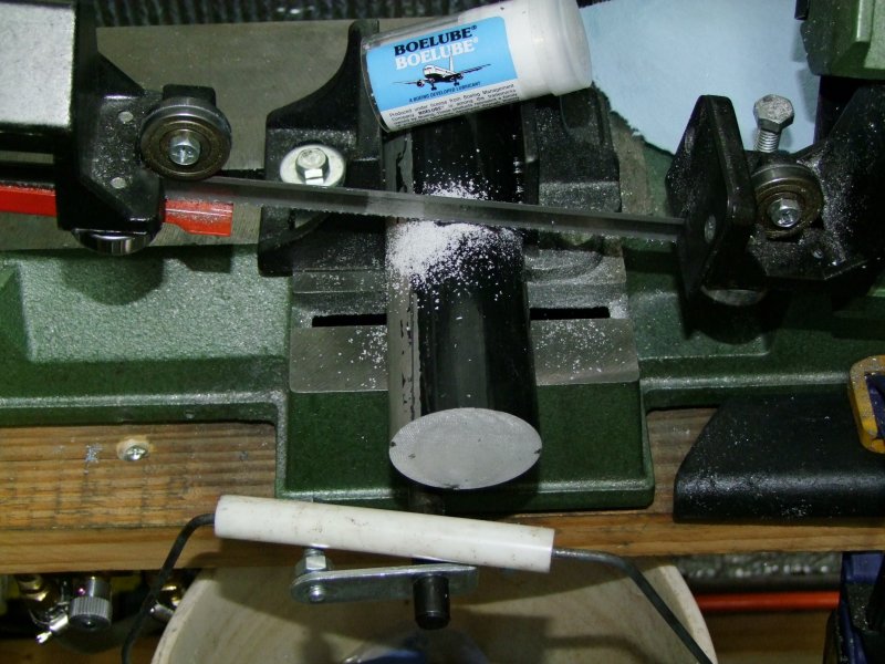
I cut it a tad longer than needed:
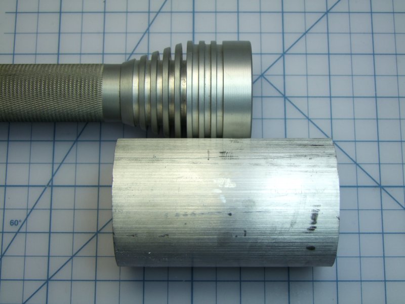
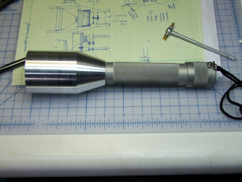
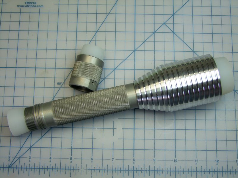
Here is the raw piece next to the original head:
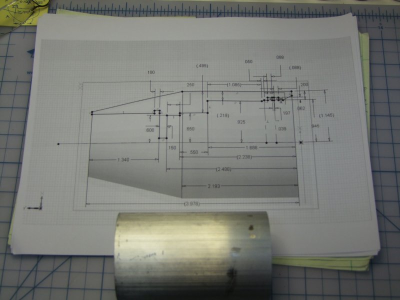
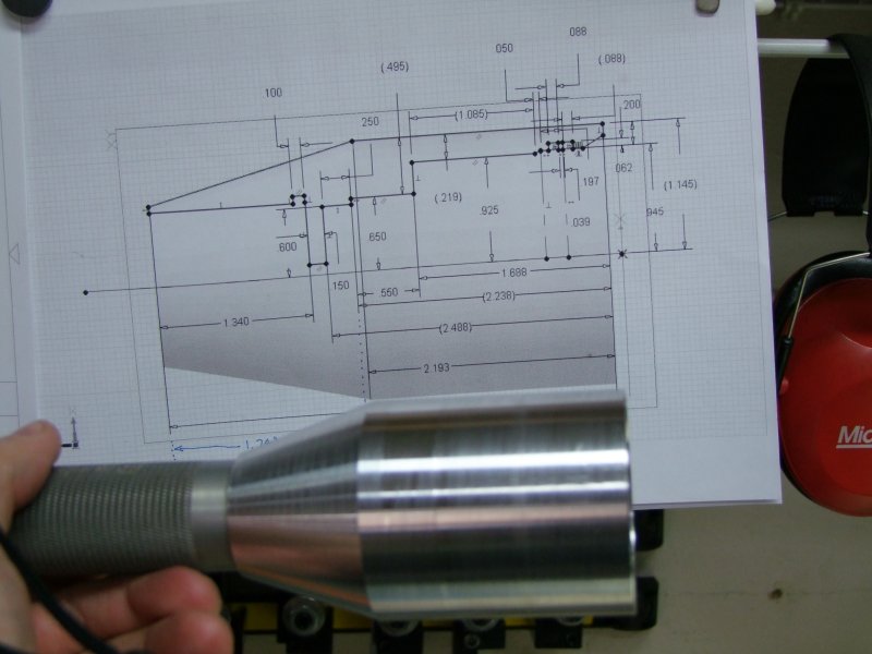
Here is the piece next to the CAD drawing:
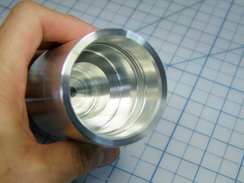
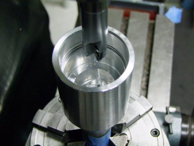
And I started work on the head:
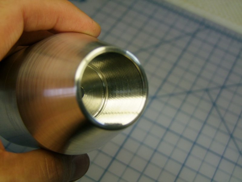
Test ID with lens:
Cut o-ring grooves:
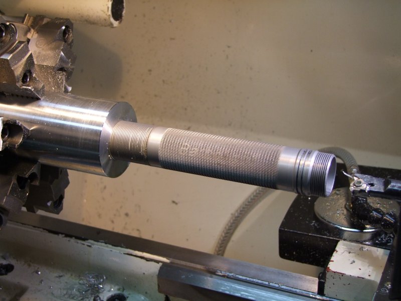
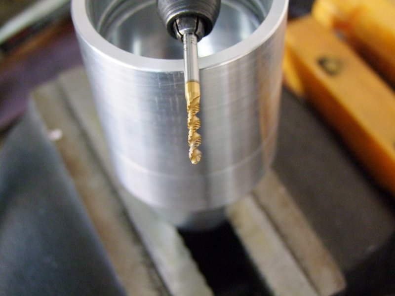
Work on the other side, to get ready to thread:
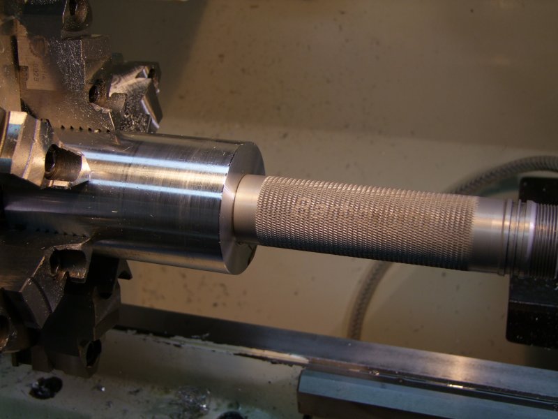
Test new metric threads:
Measure angle on original head - try to duplicate as much as possible:
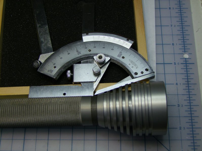
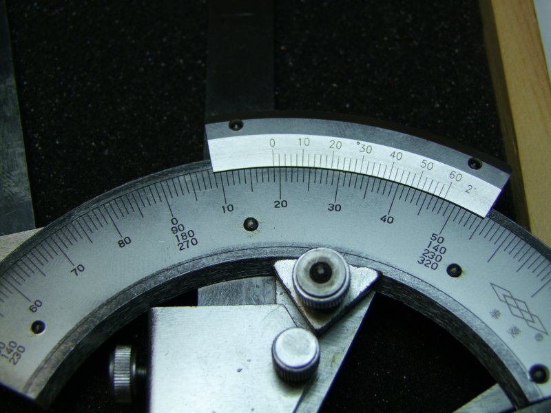
and use original head to verify the setup is fairly accurate:
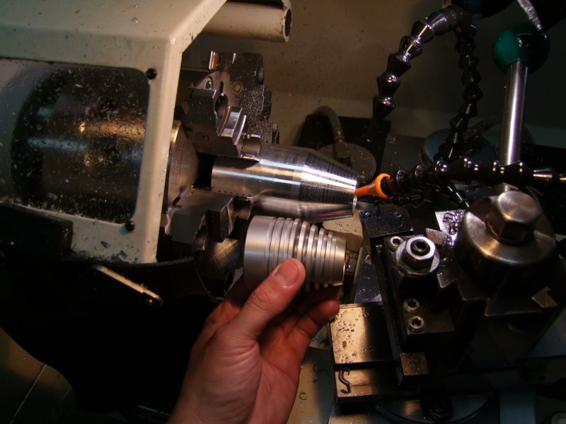
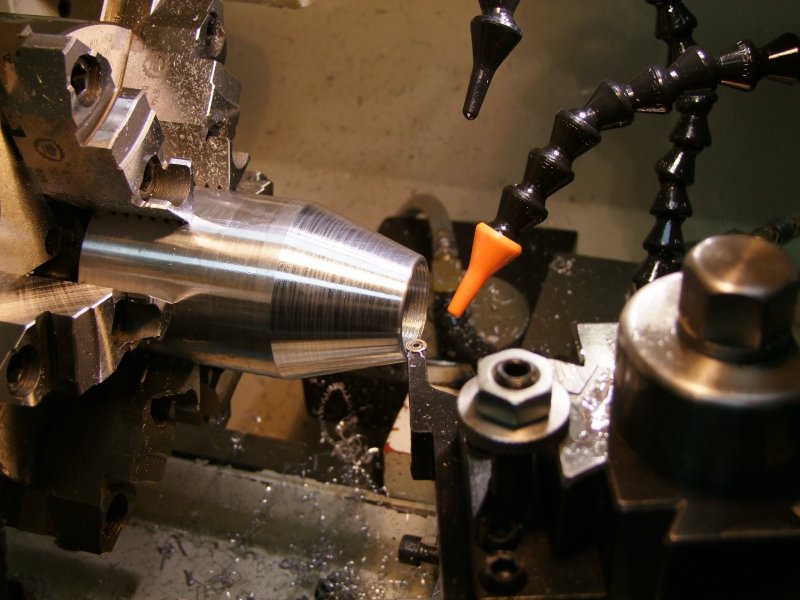
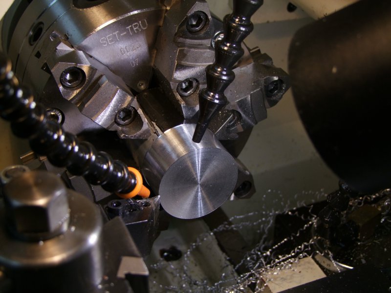
and finally make the cut (actually, many passes!):
Close enough in my book:
Round/smooth edges:
Not too bad:
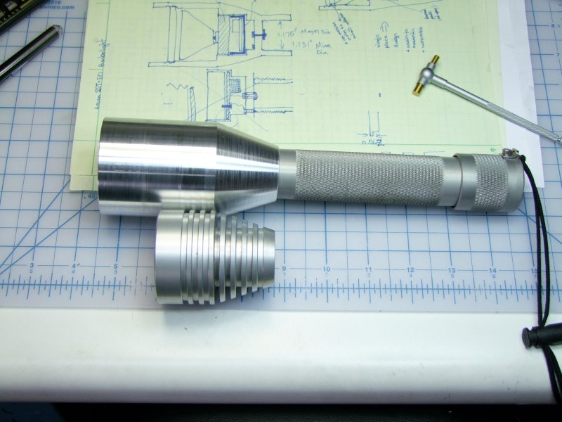
The head here is still longer than it will be in the end, but here it is resting next to some of my original paper design/ideas and then the CAD drawing:
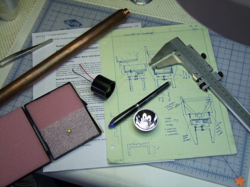
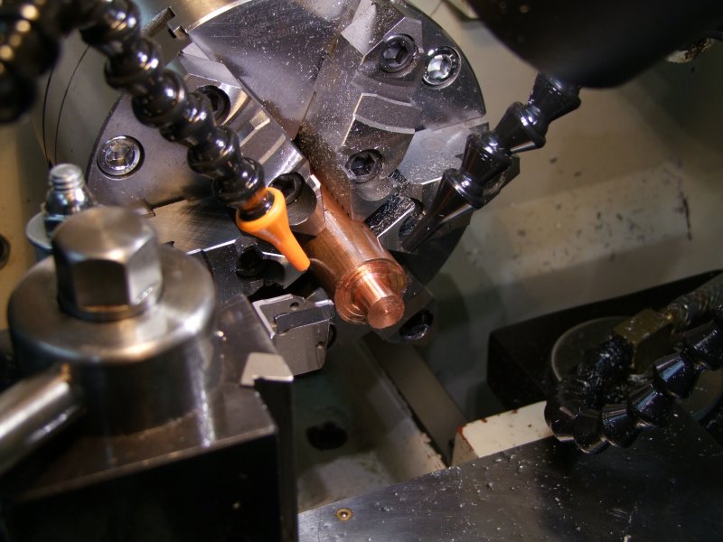
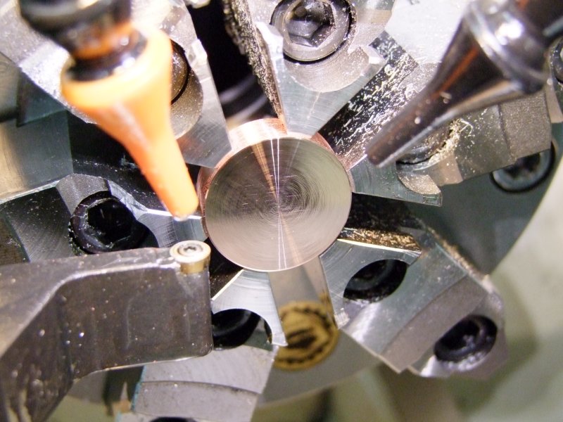
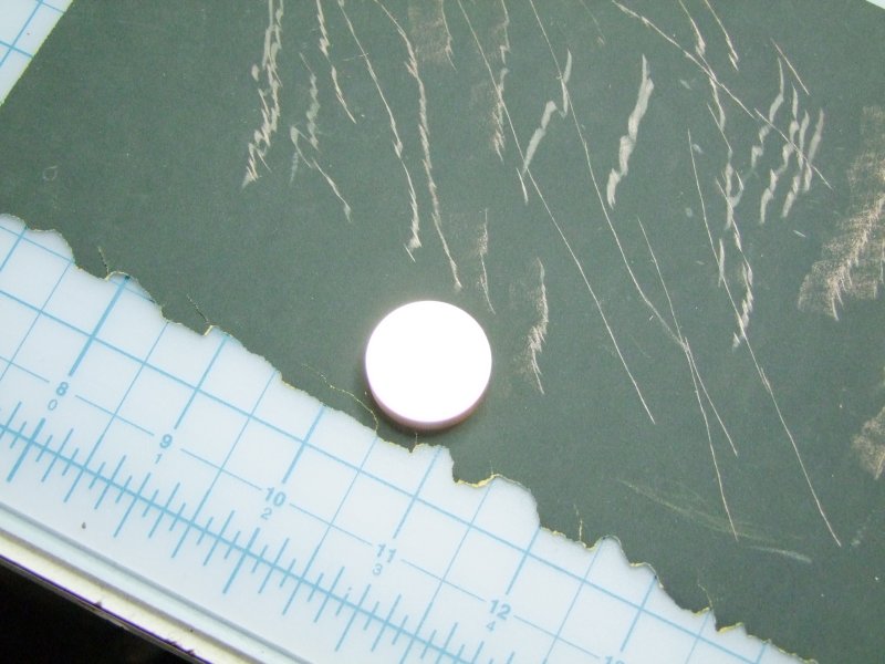
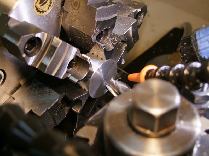
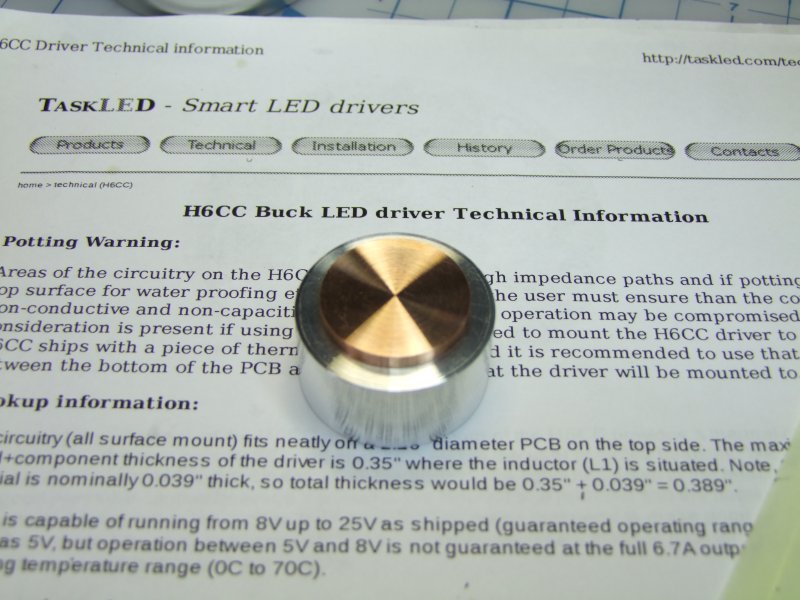
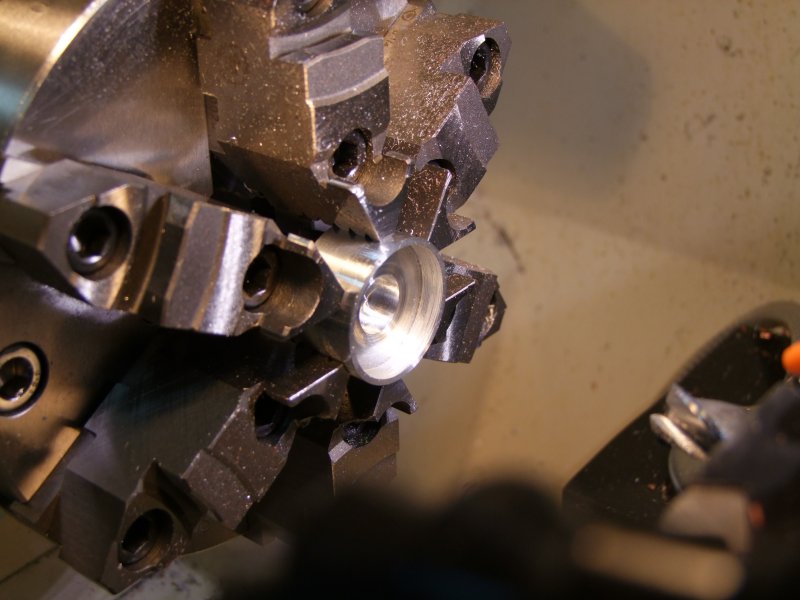
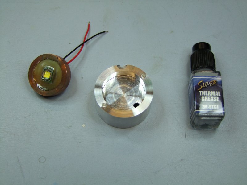
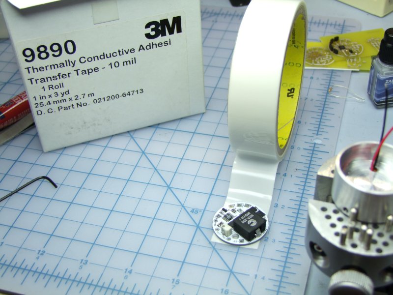
Since this build is modular and it will involve a couple of thermal transfer areas, I decided to use a copper core for the SST-50:
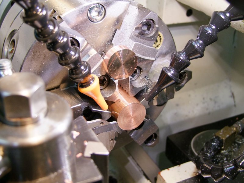
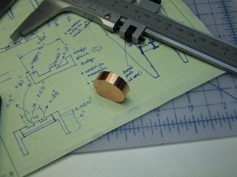
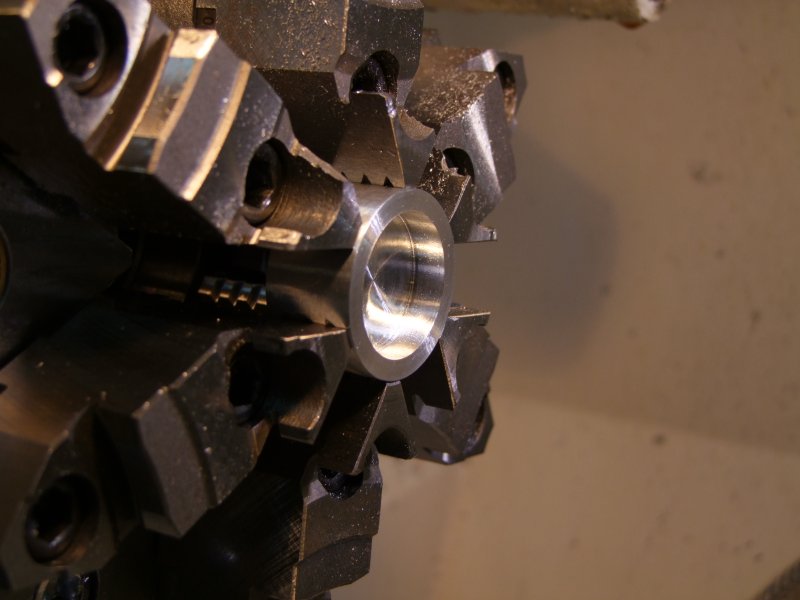
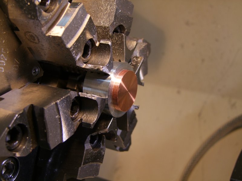
To maximize thermal transfer the piece was lightly sanded, corners smoothed out, etc.:
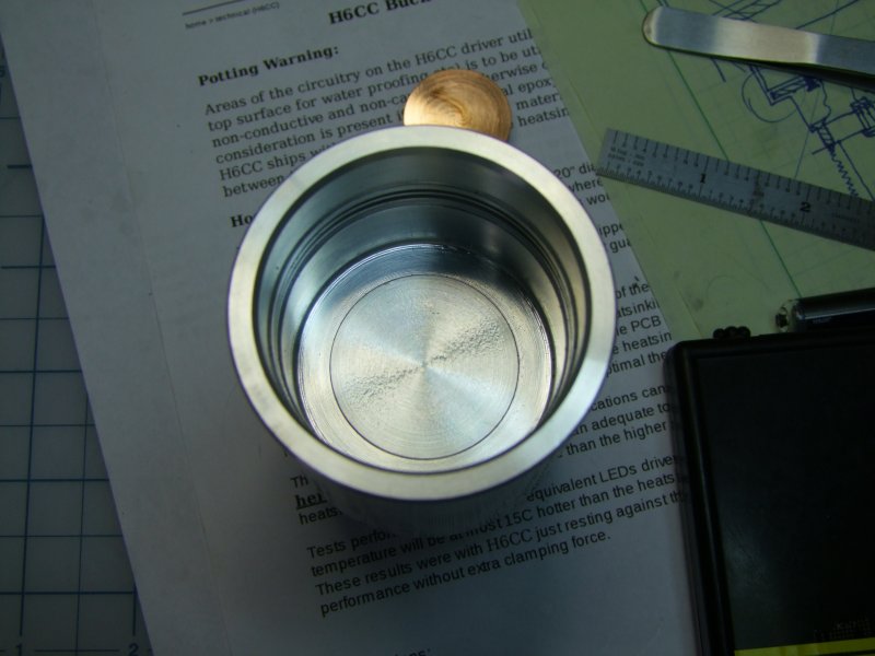
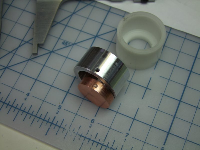
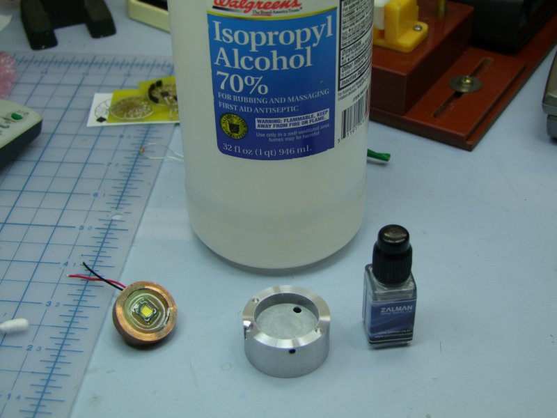
I then started to work on the heatsink/driver "module":
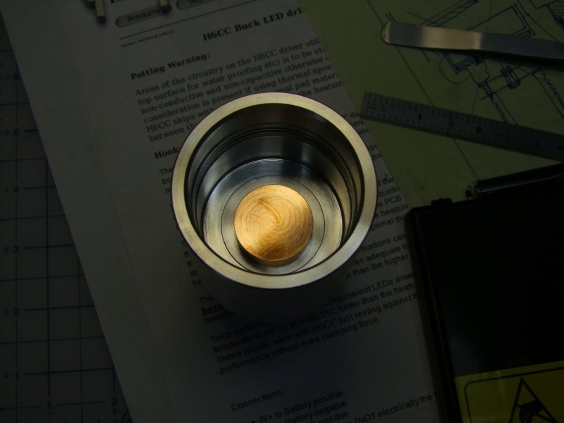
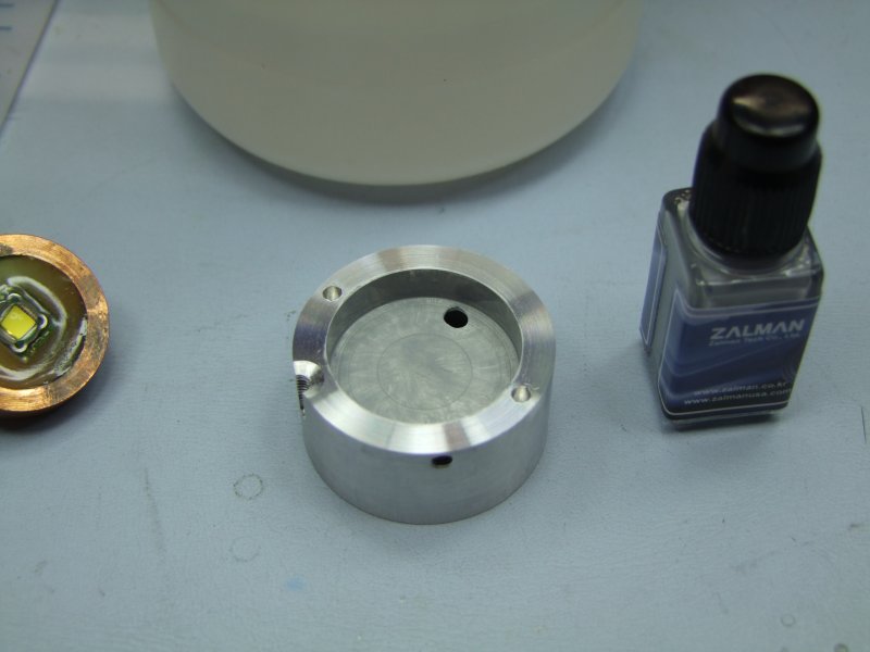
The copper core will be press fit with "thin" thermal paste and keep in place by a hidden set screw:
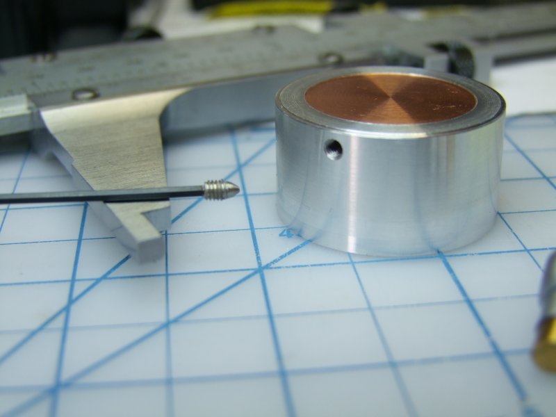
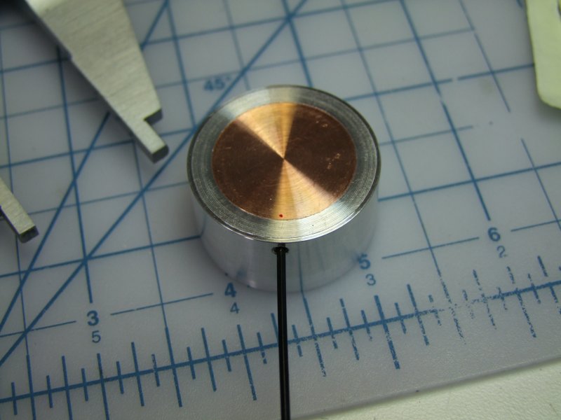
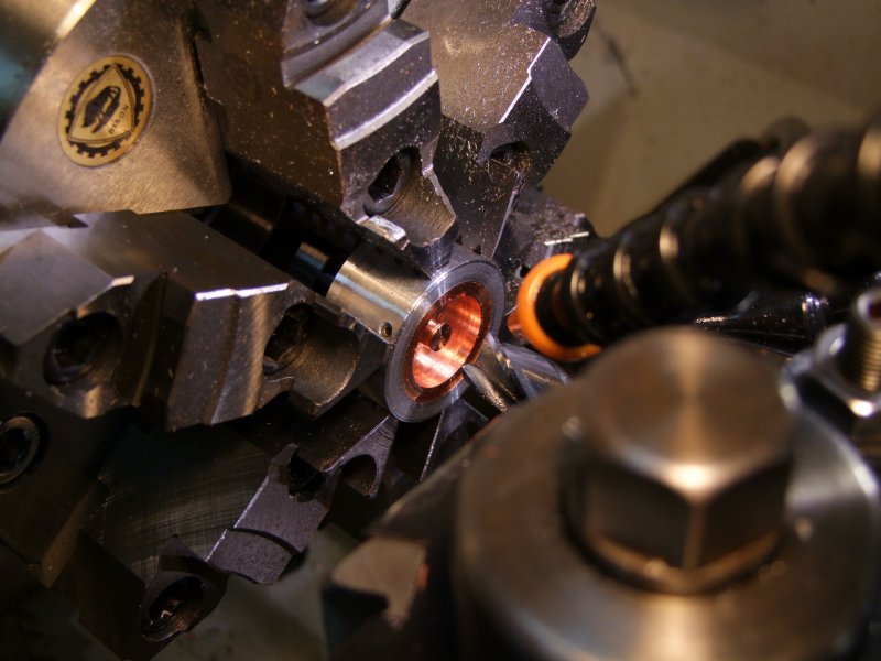
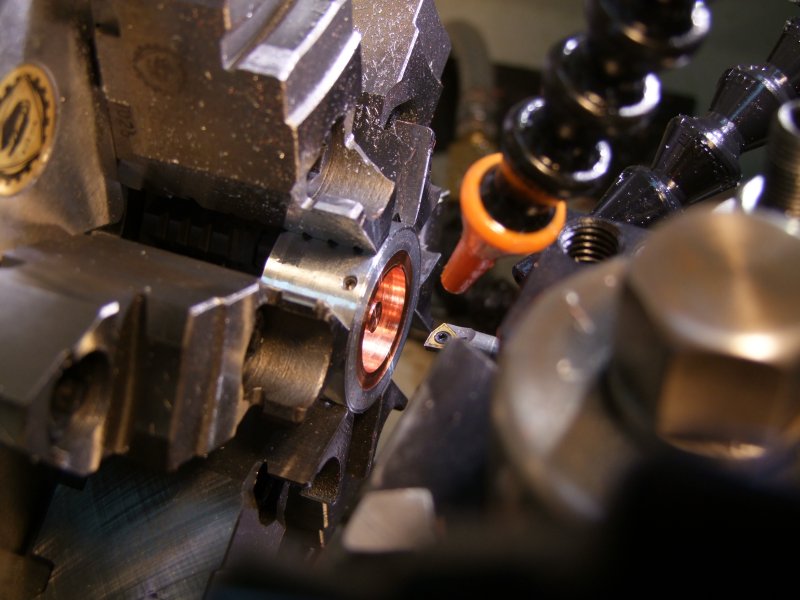
Again, for best thermal transfer, I decided to flow solder the SST-50 to the copper piece, so I made a small "post" so that I can then solder the wires from the sides:
I then worked on the other side of the module to make room for the H6CC current driver (set conservatively to 5Amps):
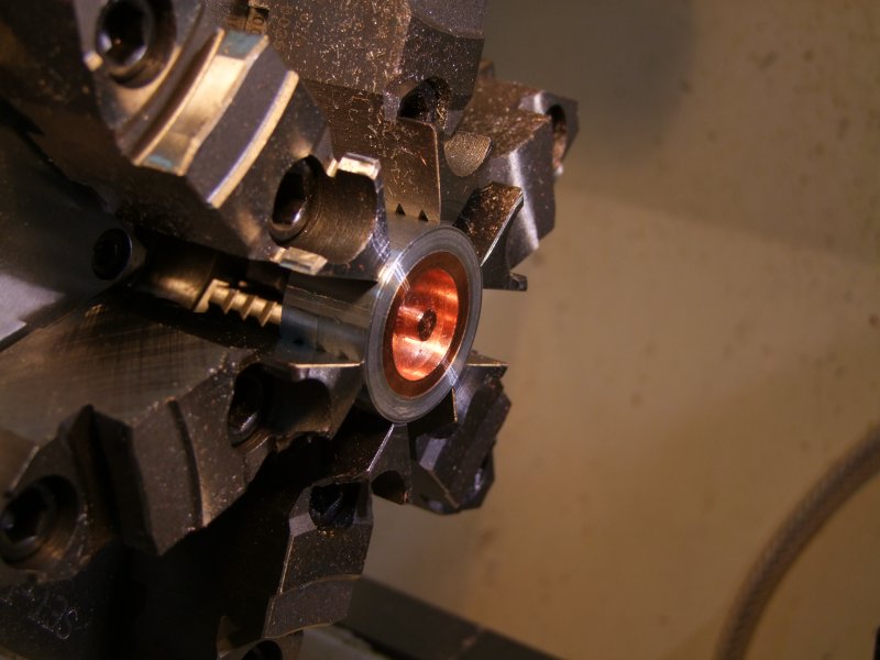
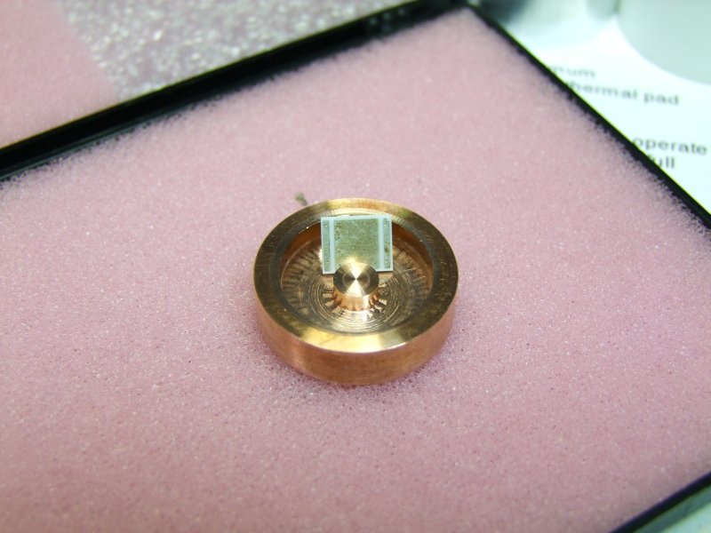
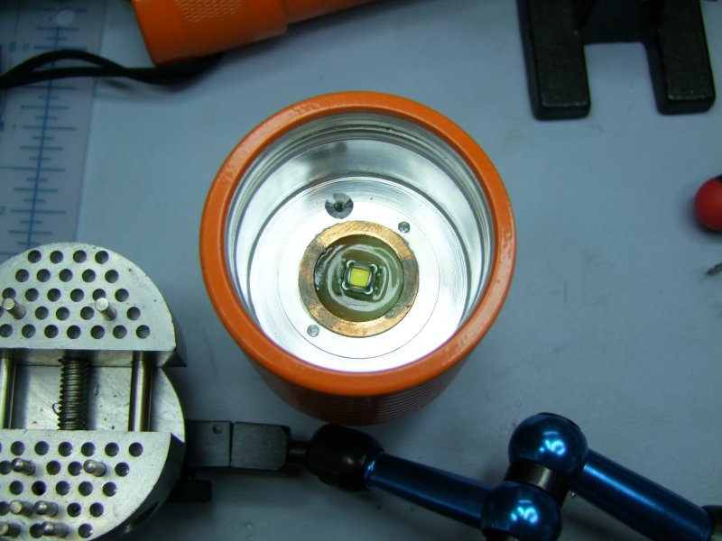
Reflow LED:
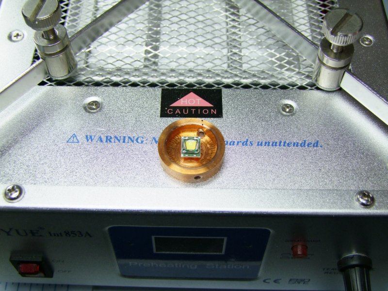
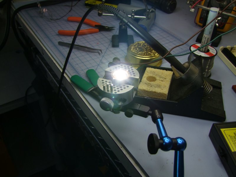
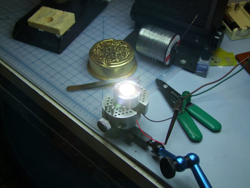
and test it to make sure I did not kill it:
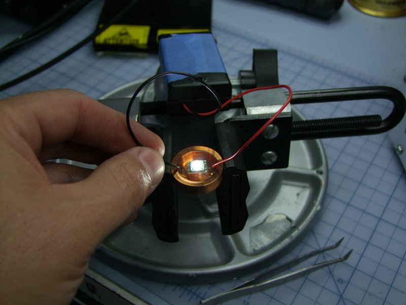
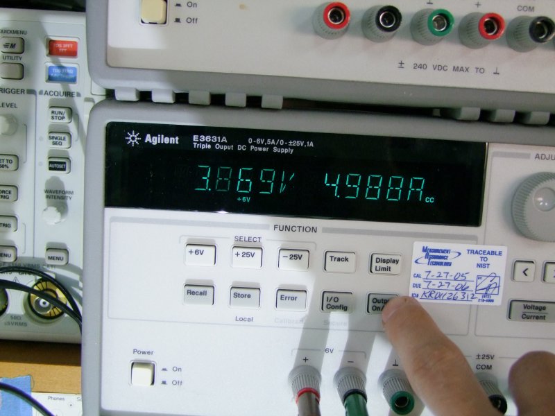
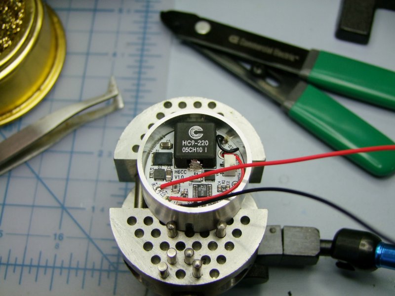
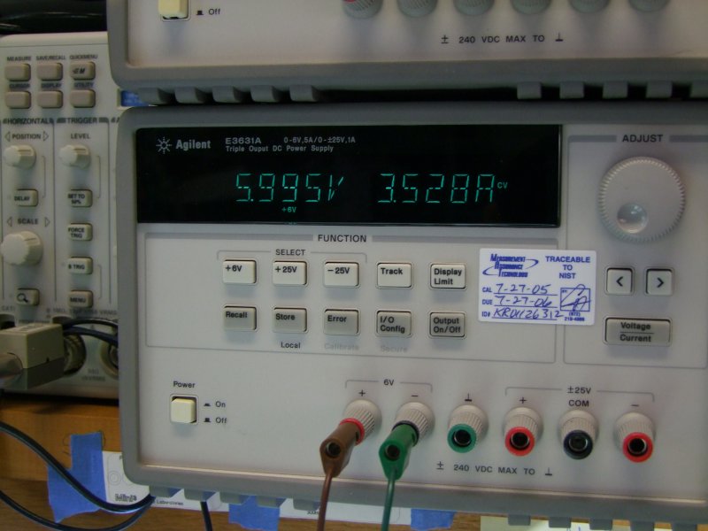
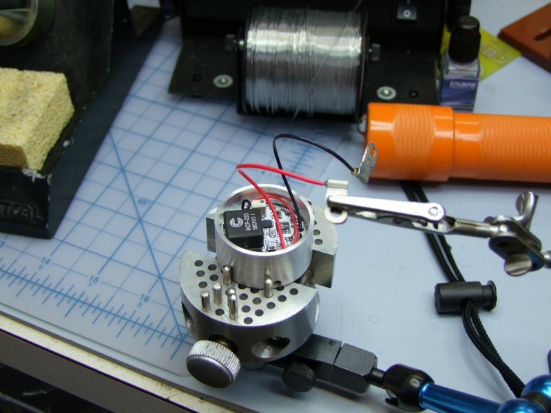
Solder wires (very hard to solder wires "blind" from the underside!) and then test it at rated current (5A, but do to the long Power Supply wires the voltage was of course higher than the actual vf):
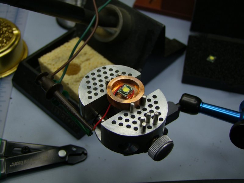
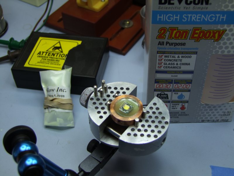
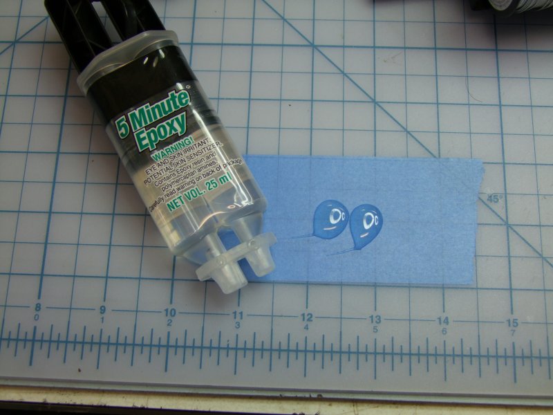
To provide mechanical strength to the solder wires, and so seal the cavity I used 2-part epoxy (even mixed glow in the dark powder for fun, although it is hard to see behind the reflector!):
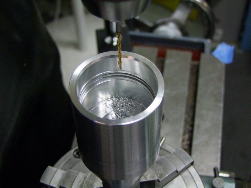
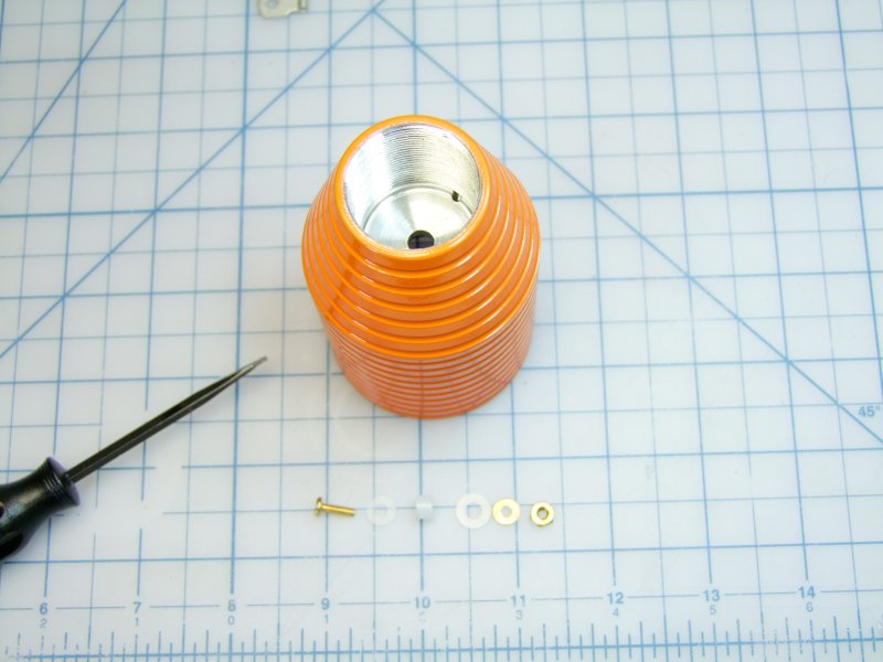
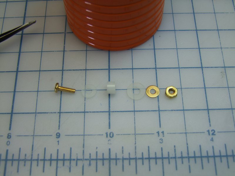
To make 100% of the solid electrical contact for the negative battery, I am using a screw through the head, through the lip of the body - no chance for anything intermittent in a diving light!:
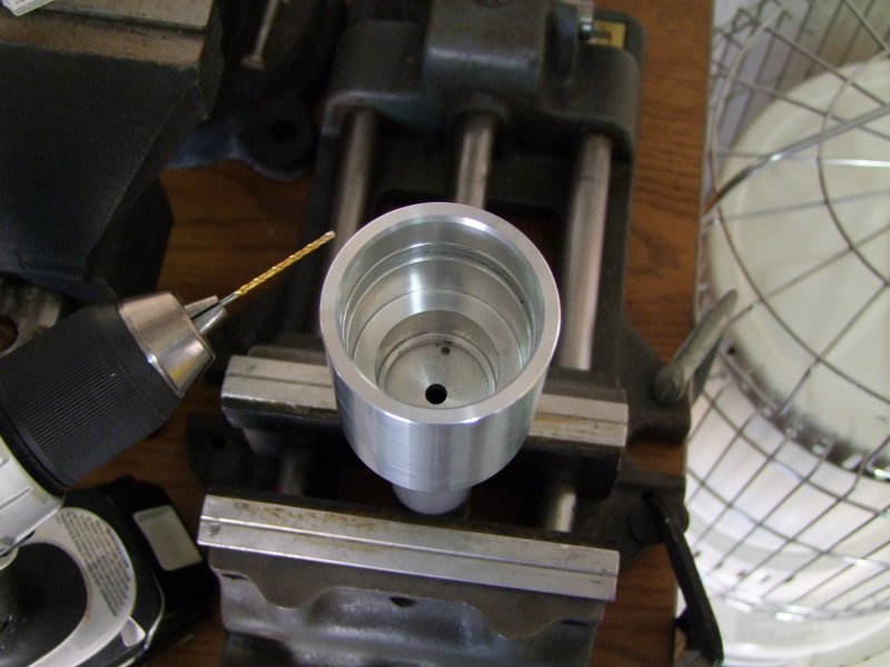
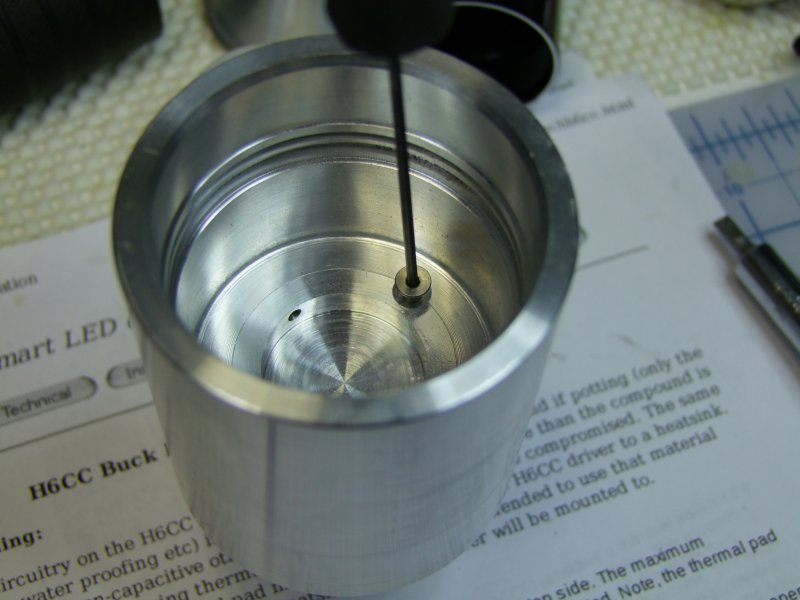
I then milled a relief area for the screw head:
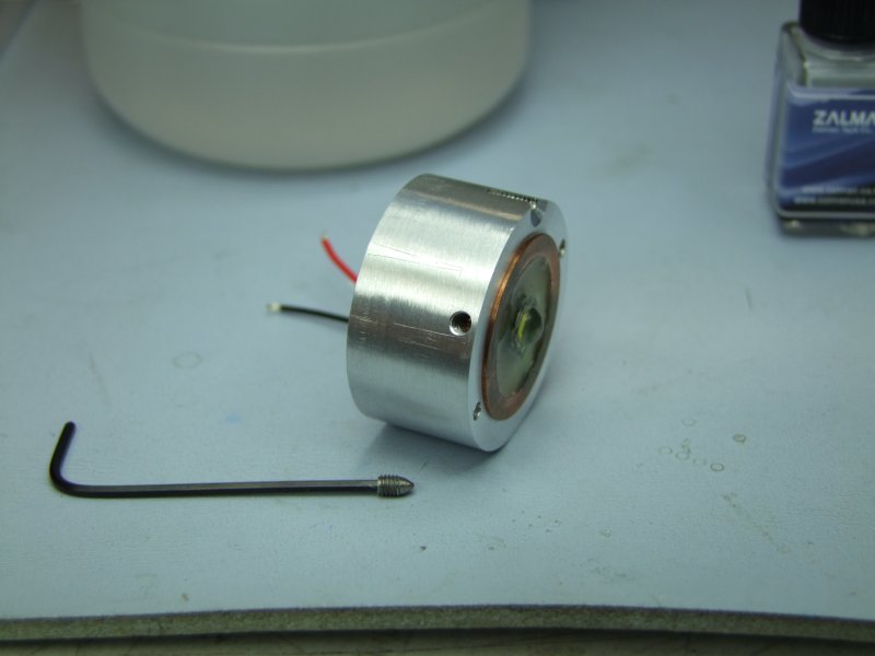
I am also using a screw to keep the LED/driver module firmly in place:
Since it is a slight press fit, I drilled two small holes so that I could use thin nose pliers to align the module with the screw hole:
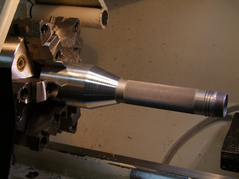
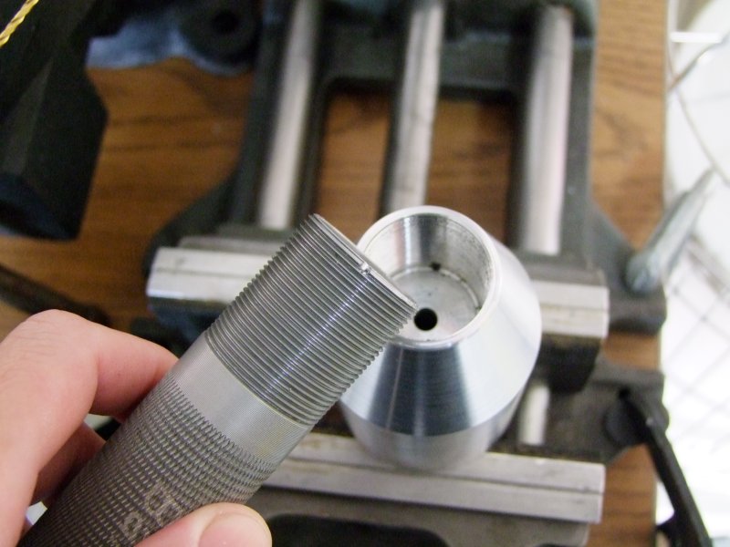
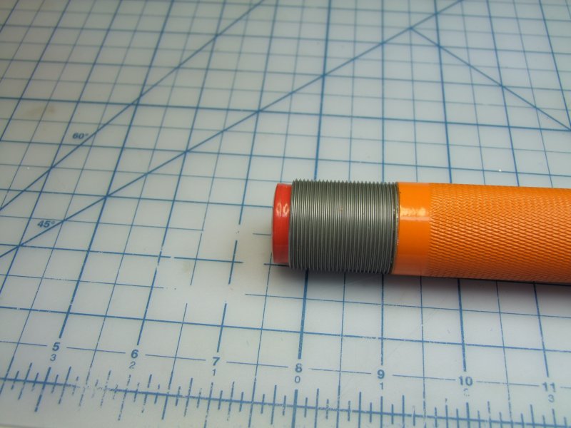
Since I have to trim the length of the head and since the head is too smooth and slippery, I cut some shallow grooves:
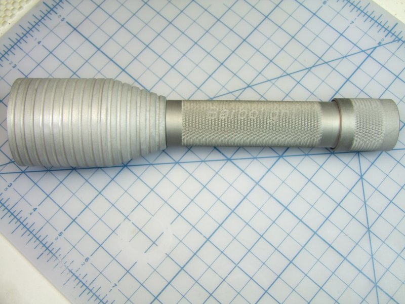
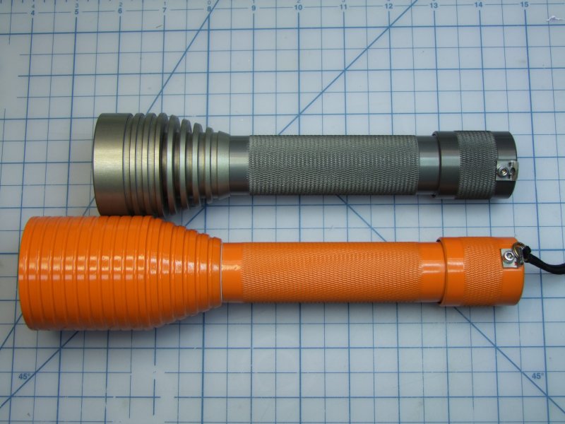
Here is now the finished head, next to the original one. The extra length is for the driver/module/wires/etc.. Is is also much stronger (although heavier) than the original head:
I then did a light boring to fit the "fatty" IRM C cells:
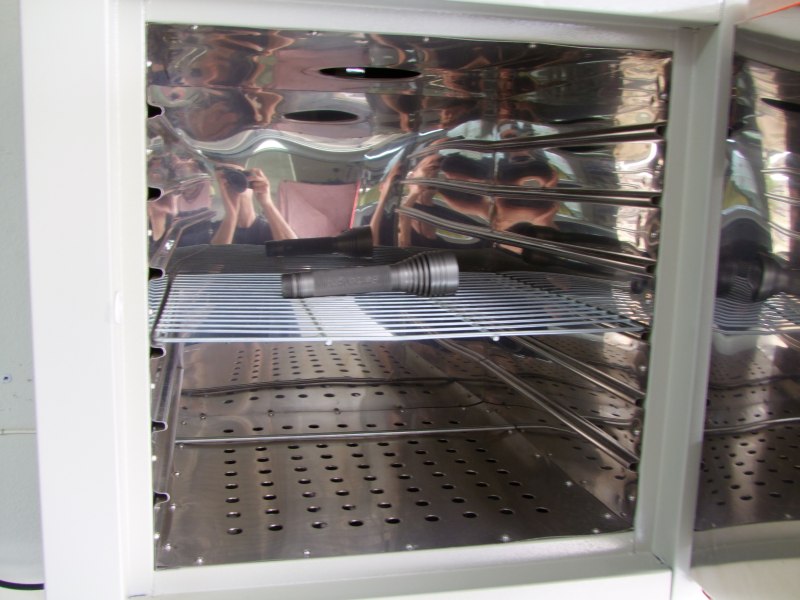
To prepare for powder coating, I bought some silicon plugs (these stand 500+ F, far lower than the 400F needed for the coating to take in the oven):
Unfortunately for the shinny finish, I had to sandblast the surface to aid in the adhesion of the powder coating:
I am using a copper wire through the center to ensure good electrical contact (critical for powder coating):
So after getting parts cleaned and pre-heated (to evaporate any residue):
I then coated them:
I then re-assembled the tailcap:
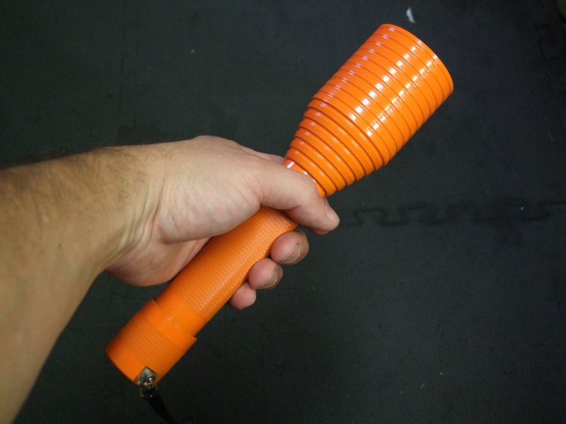
To give you an idea of scale/size:
With the IMR cells, this is how little the spring has to be compressed:
Here I am assembling the copper core to the heatsink module. The fit was so good, that even after applying this thin liquid, it became a press fit:
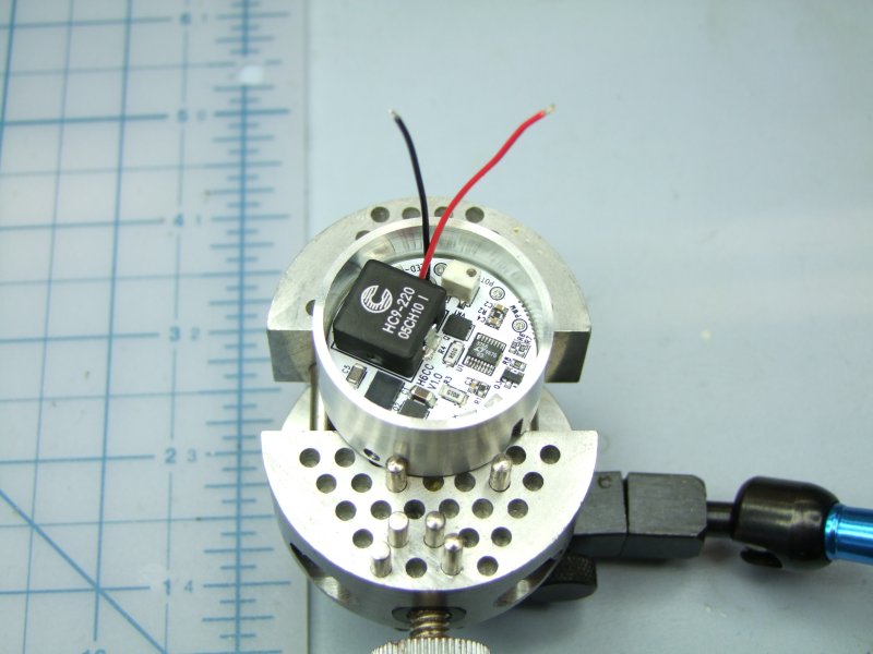
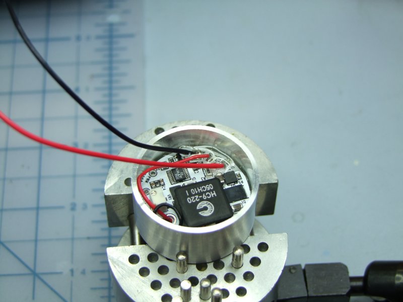
I then soldered and setup the H6CC to the other side of the module:
I then tested everything again:
I then applied a little epoxy to make sure things stay put:
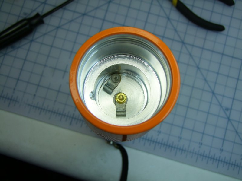
This is the center conductor to the Bat +:
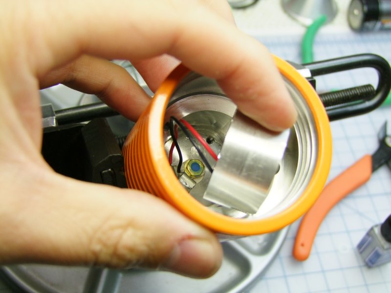
And this is how the module connects to the Bat - and Bat +:
I did a test fit and test for operation:
And then, with the head not fully screwed in, another test using real IMR cells:
I guess it is a coincidence that the all parts, including the cells are orange!:
I now have to make a custom fitted ring to hold the reflector in place:
I then sanded it for a light sliding fit in the head:
Once I was happy with the fit, I epoxied the centering ring to the reflector:
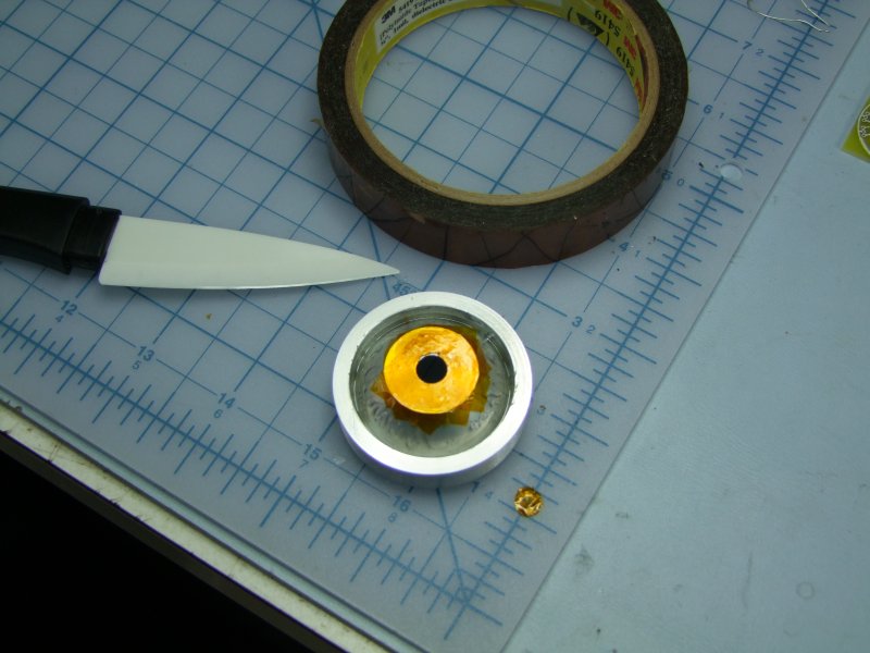
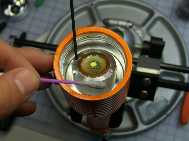
A coat of Krapton tape to make sure I can't have any shorts with the LED:
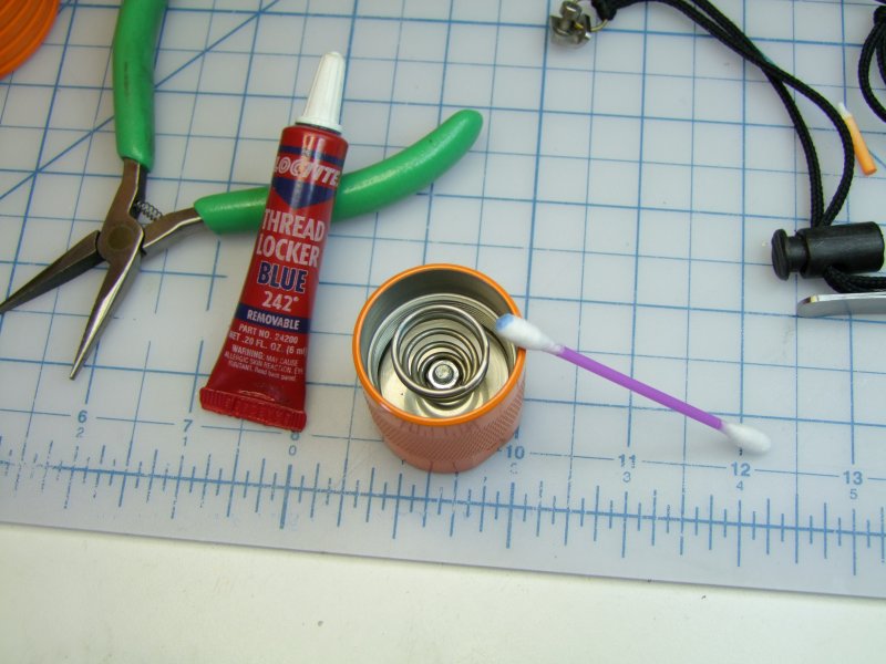
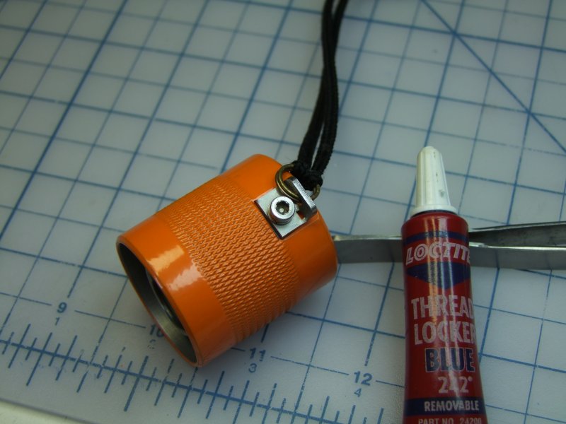
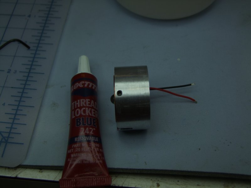
Here I am doing the final assembly (blue stuff is Loctite):
Seal the head to the battery tube (had to access sealant from side as top was dry!):
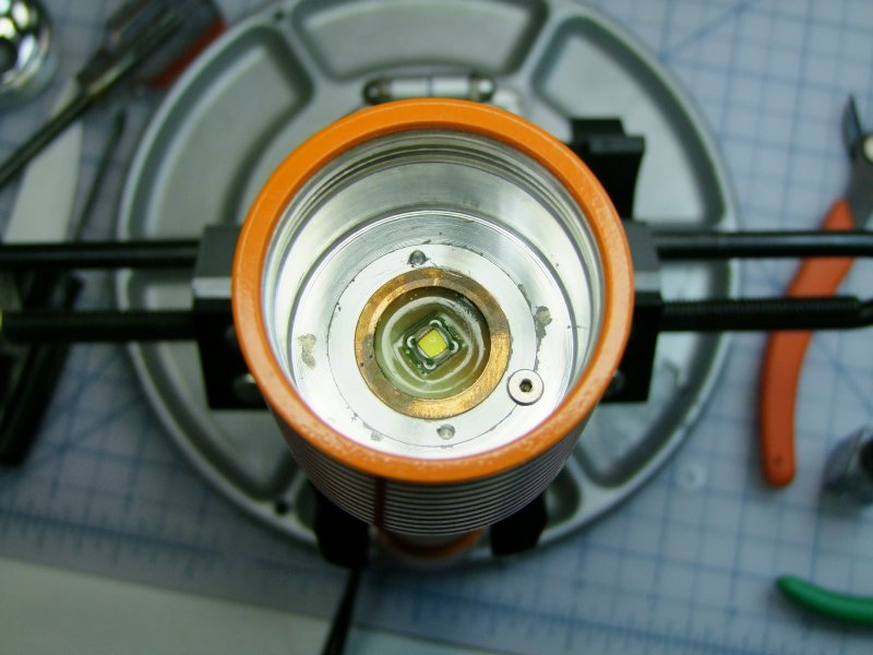
Lightly coat module with thermal paste:
and seat in place (here I am not done cleaning the interior - not that anyone will see this part anyway, but that is the way I am!):
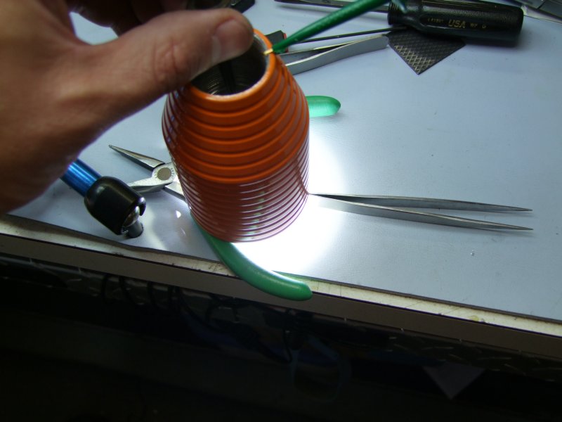
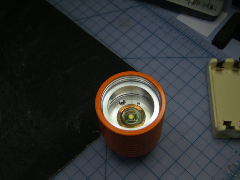
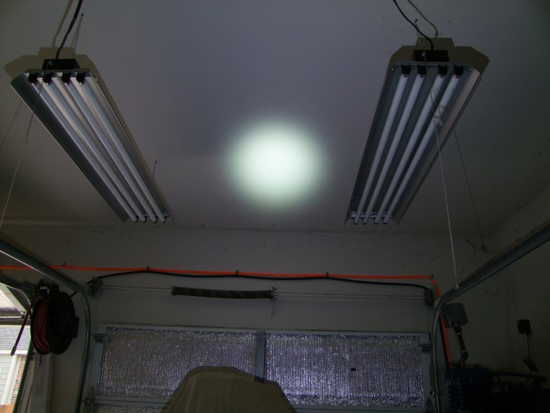
and finally test the beam (unfortunately during bright daylight (see garage door open on left!):
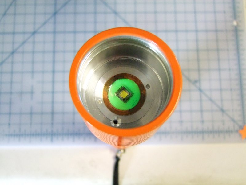
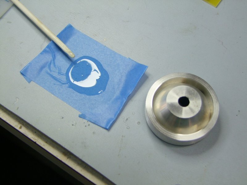
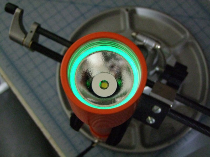
I then took the reflector out, coated the edge with epoxy and glow in the dark powder:
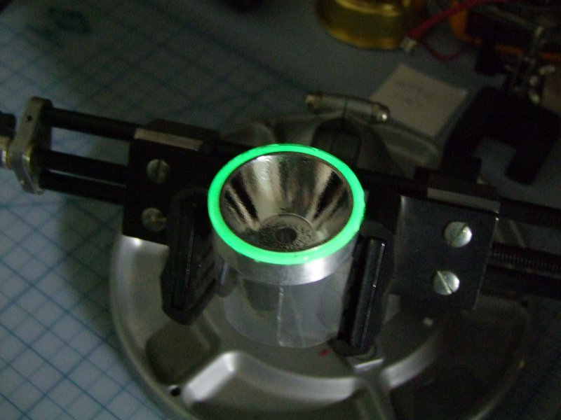
In this photo you can see a "little" bit of the glow around the LED as well:
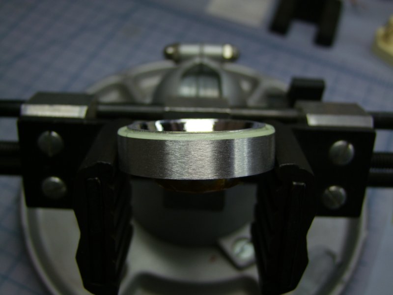
This o-ring on top of the reflector (once you install the lens) keeps the reflector in place and with zero rattles:
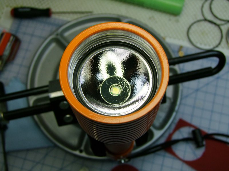
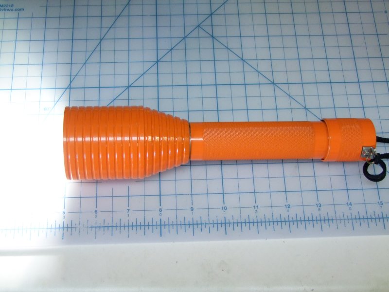
Here is the finished light:
Next to the warm MC-E version I did for the same owner back in January of this year:
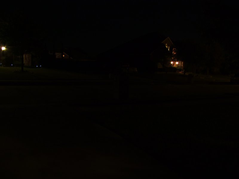
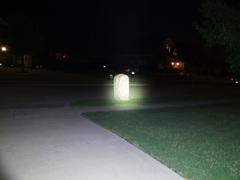
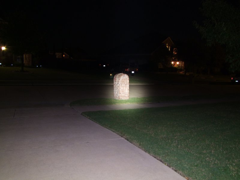
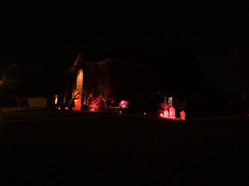
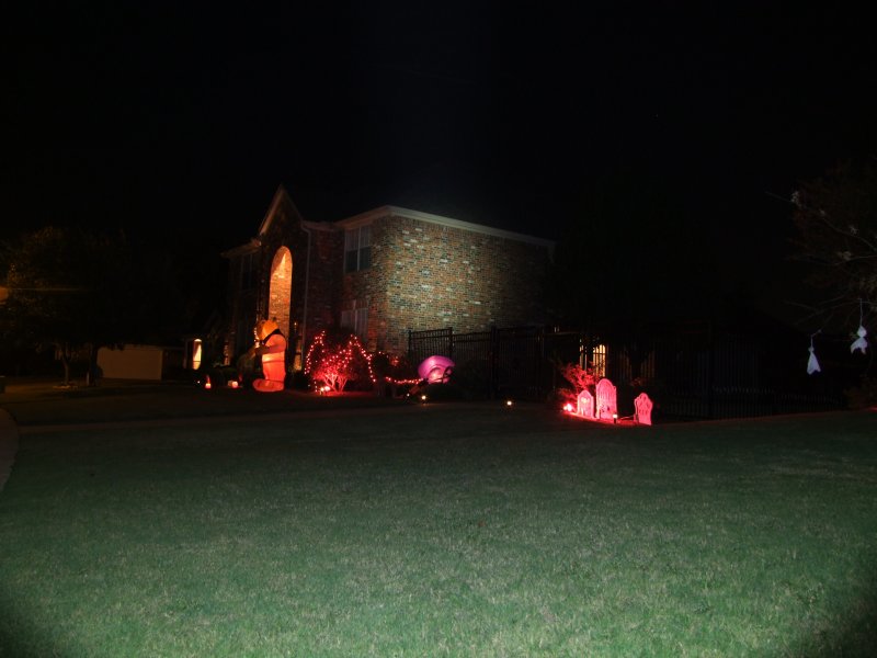
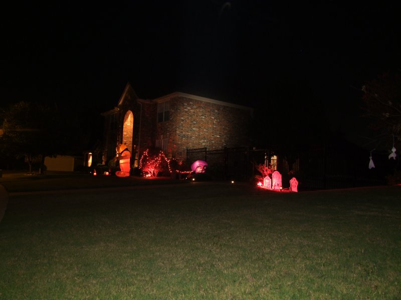
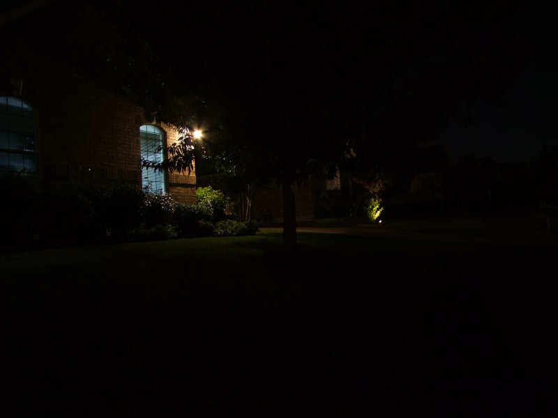
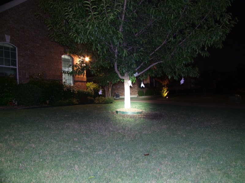
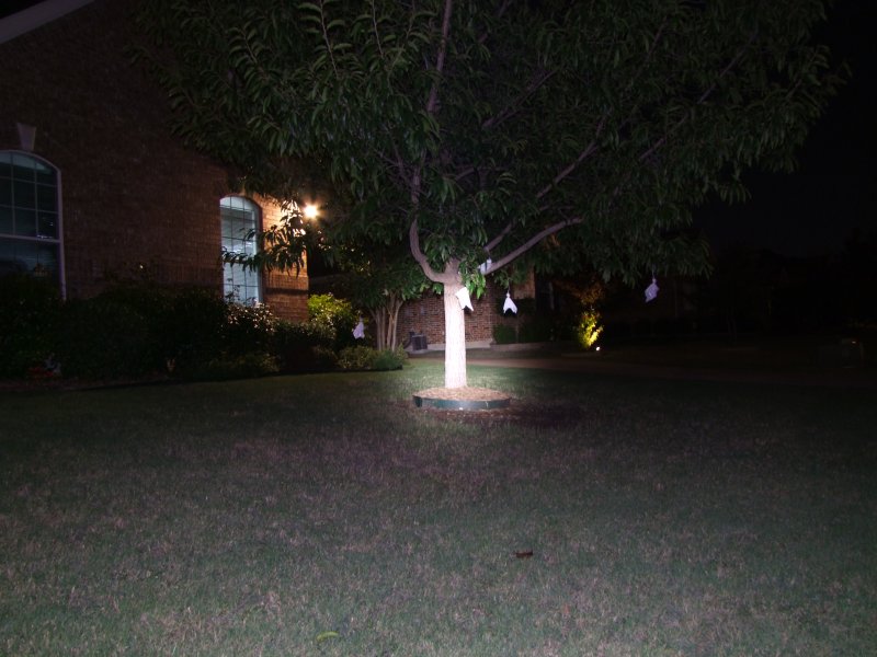
I will post some beamshots tonight when it gets dark again
Will
But for this one the owner wanted something more, something unique, and he suggested the SST-50. I suggested using the whole body (3x cells) for decent runtimes with the SST-50, but problem was the H6CC driver from George (www.taskled.com) was not yet available (Nov 2009), so this project was on hold for many months waiting on an efficient driver solution that could handle 3x LiIon cells. Once the driver was available, then another challenge was found: there is no way to fit the H6CC in the U9 host - too big for the body, and no room in the head. I suggested making a completely new, larger head from scratch, the owner agreed. But the head needed to have a couple of critical dimensions, so I decided to do the head design in a 3D package. So I bought Alibre Expert software and did the head design in the computer. Once I was happy with the design, I then started making the new head. I told the owner that I have a new Powder Coating system, and he said he would like his new light in Orange, so after many weeks of practicing/learning how to powder coat, I was able to get this light coated properly.
All in all I have been working on this second light for about 11 months, but it is now finished - I hope the owner will be happy with the result
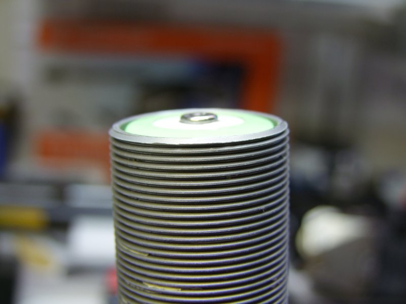
Here is how the light looked like when I got it last year:
So I started disassembly:
Heating the factory epoxy to remove the head:
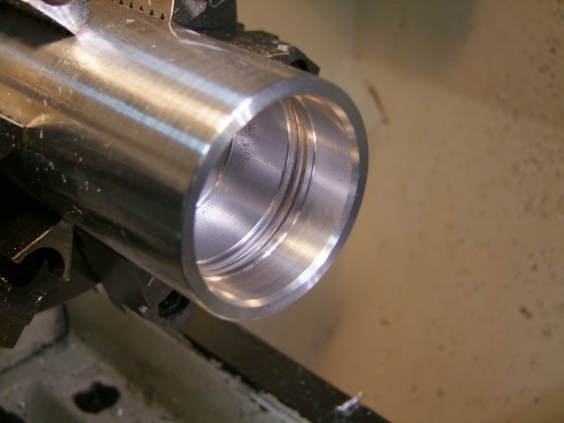
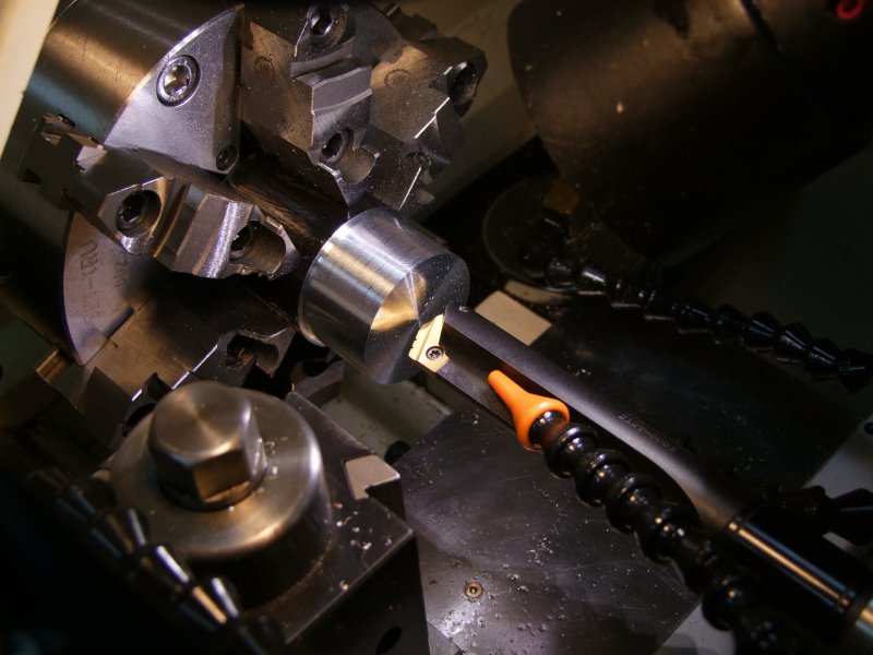
Barbolight uses a proven method for water-proofing the front lens, but it is one of high precision on the o-rings, lens OD, and o-ring groove. Since I have never done this before, I first practiced with a piece of scrap. First got the ID to be a sliding fit with the lens (I also have a spare lens to play with):
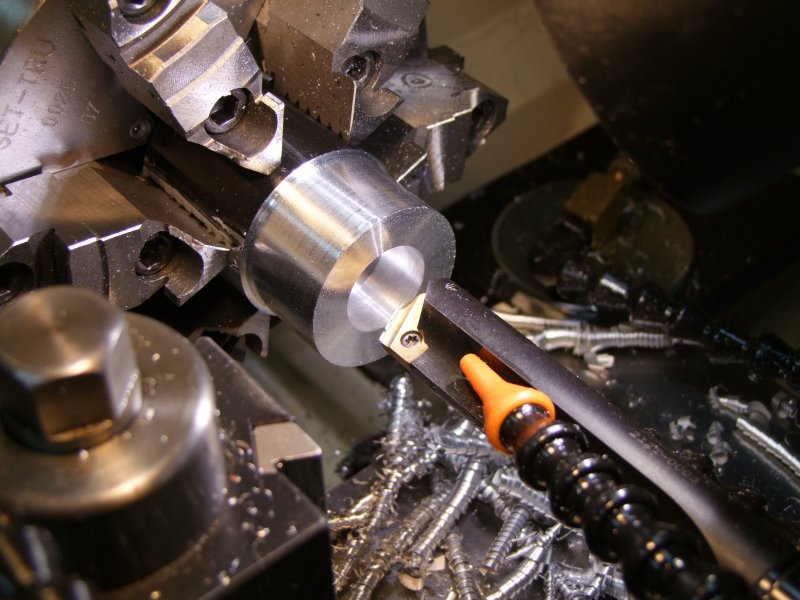
and then cut the o-ring grooves (I did two sets of them):
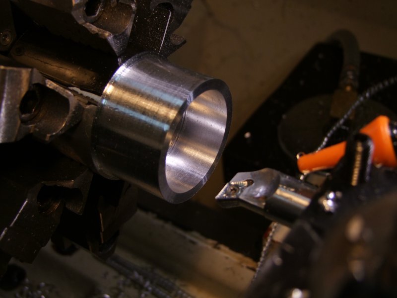
I tested the o-ring and lens (original head to the right side). It works really well:
I then played with an SST-50 mounted on a Mag D heatsink with various reflectors. In the end I selected a shallow reflector that worked well, which is the same one I used for the warm MC-E conversion earlier:
Size comparison of the original host, the original 3x NiMH pack, the will-always-be-missed "C" AW LiIon cells, and the newer but-larger-than-a-true-C-cell IMR:
With the tailcap fully inserted, and the spring fully rested, this is how things look like. I did several measurements on the cells, which allowed me keep the original tailcap spring since it meant that I could use either the longer Black/IMR cells since the spring will take up the difference
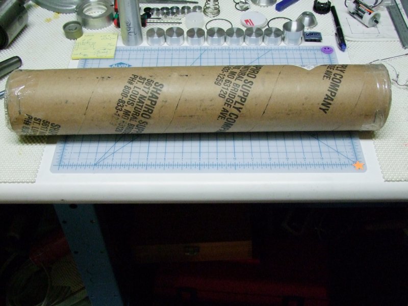
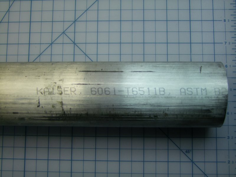
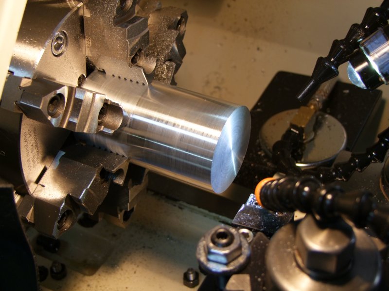
So the big day arrived when I got the new Al piece for the new head:
I cut it a tad longer than needed:
Here is the raw piece next to the original head:
Here is the piece next to the CAD drawing:
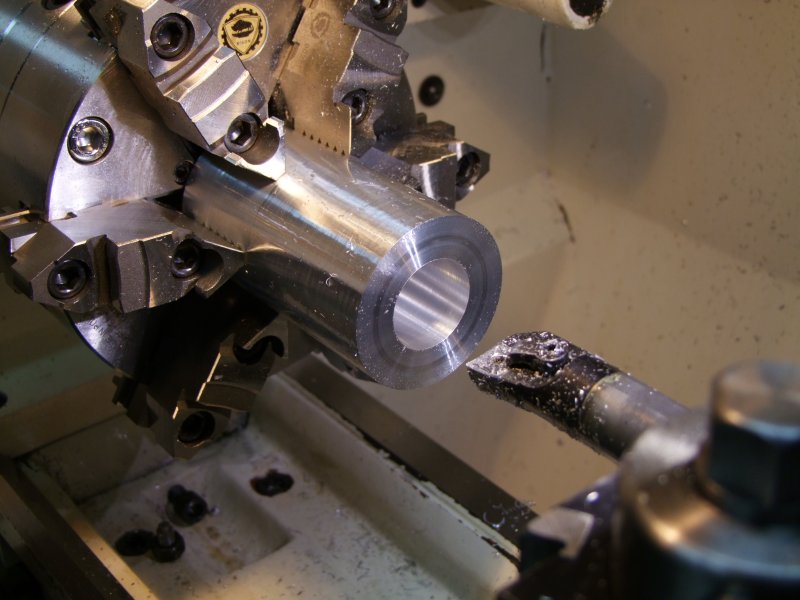
And I started work on the head:
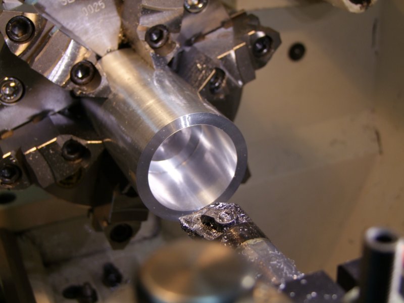
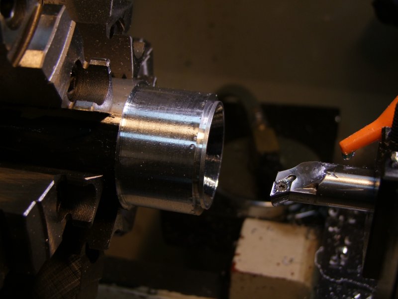
Test ID with lens:
Cut o-ring grooves:
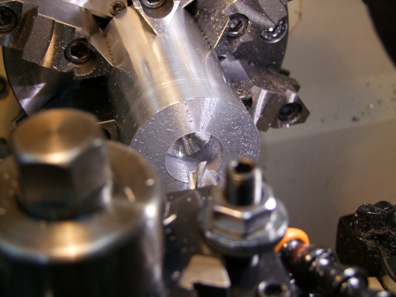
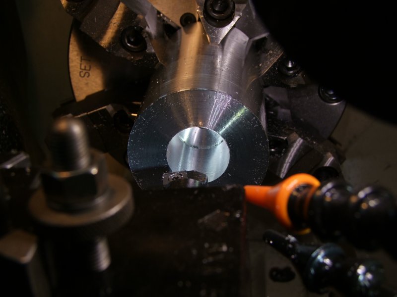
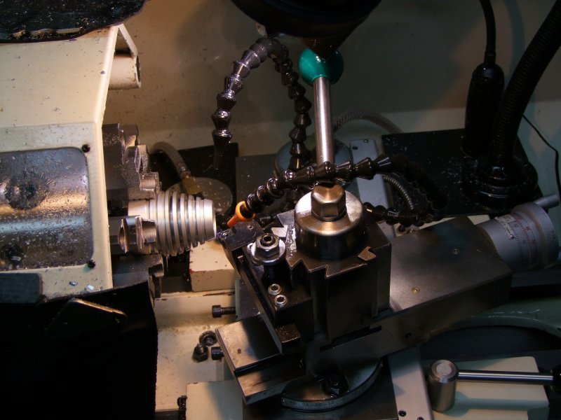
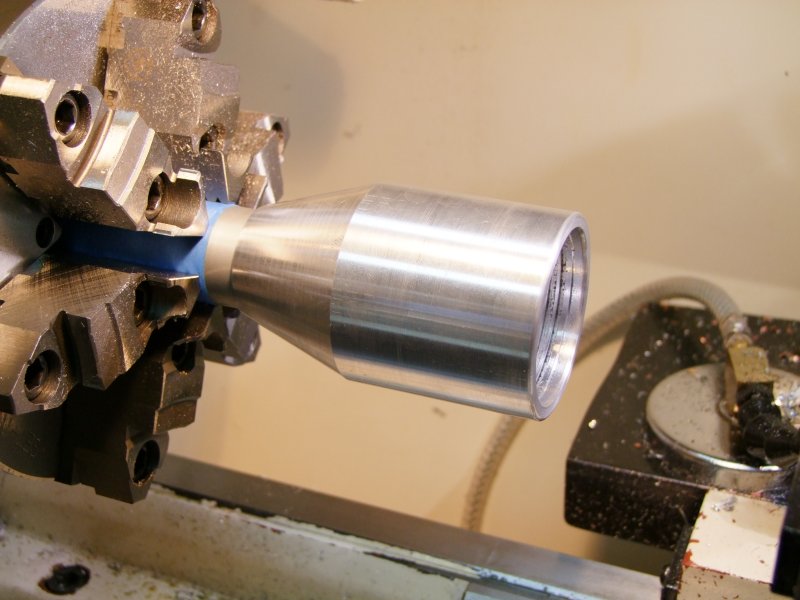
Work on the other side, to get ready to thread:
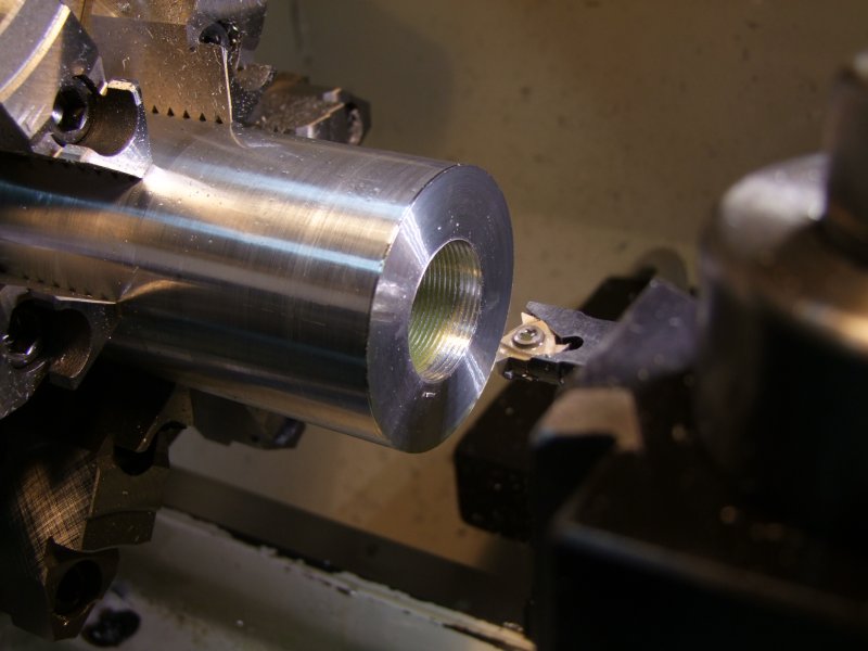
Test new metric threads:
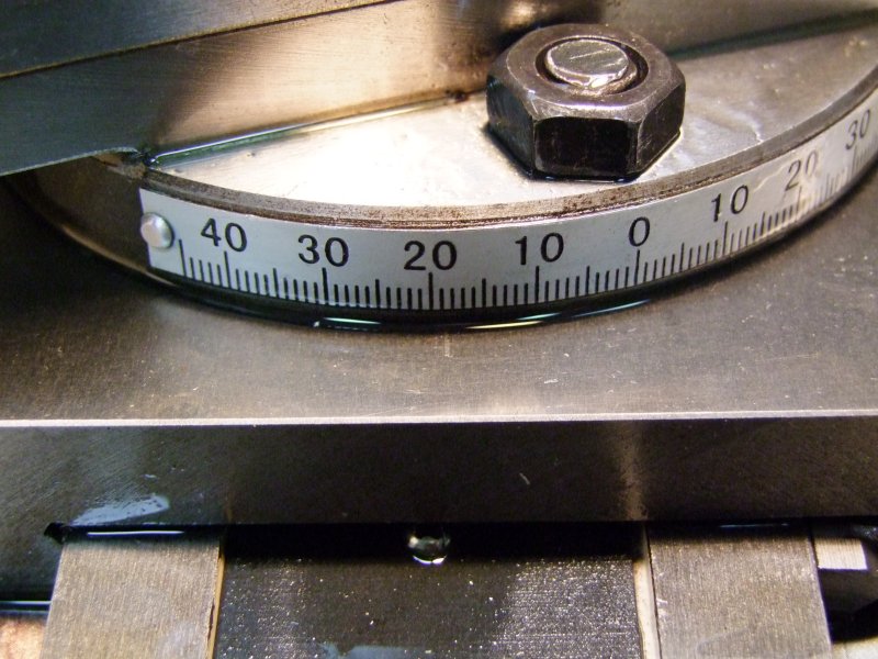
Measure angle on original head - try to duplicate as much as possible:
and use original head to verify the setup is fairly accurate:
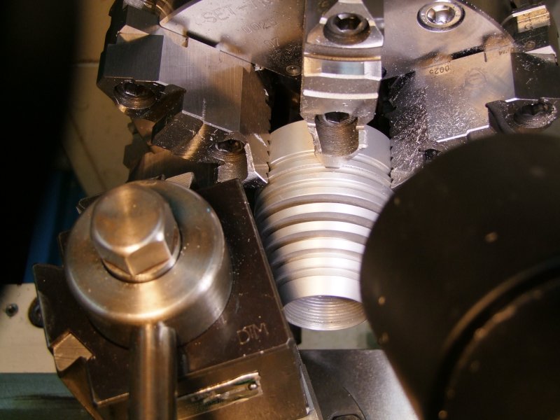
and finally make the cut (actually, many passes!):
Close enough in my book:
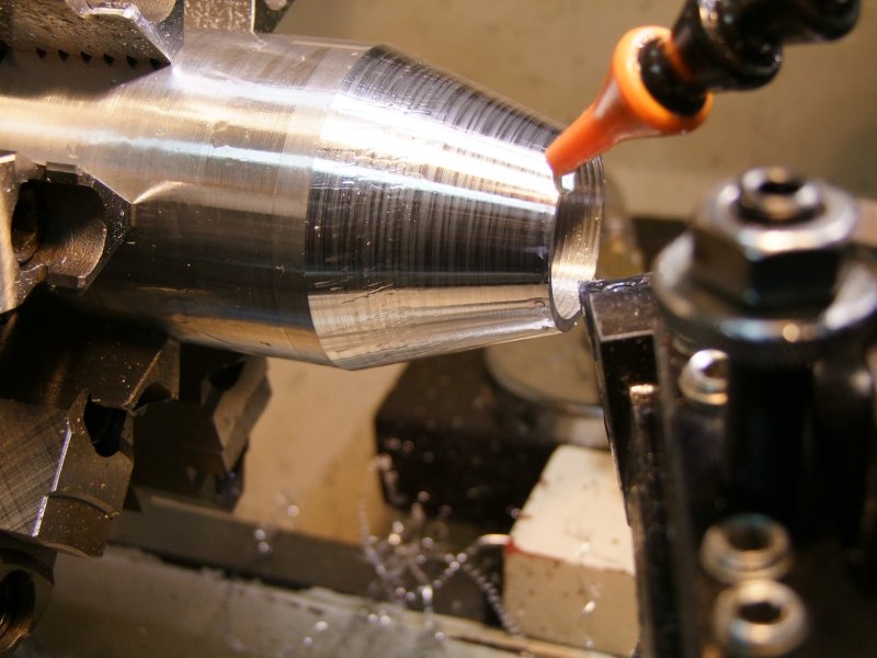
Round/smooth edges:
Not too bad:
The head here is still longer than it will be in the end, but here it is resting next to some of my original paper design/ideas and then the CAD drawing:
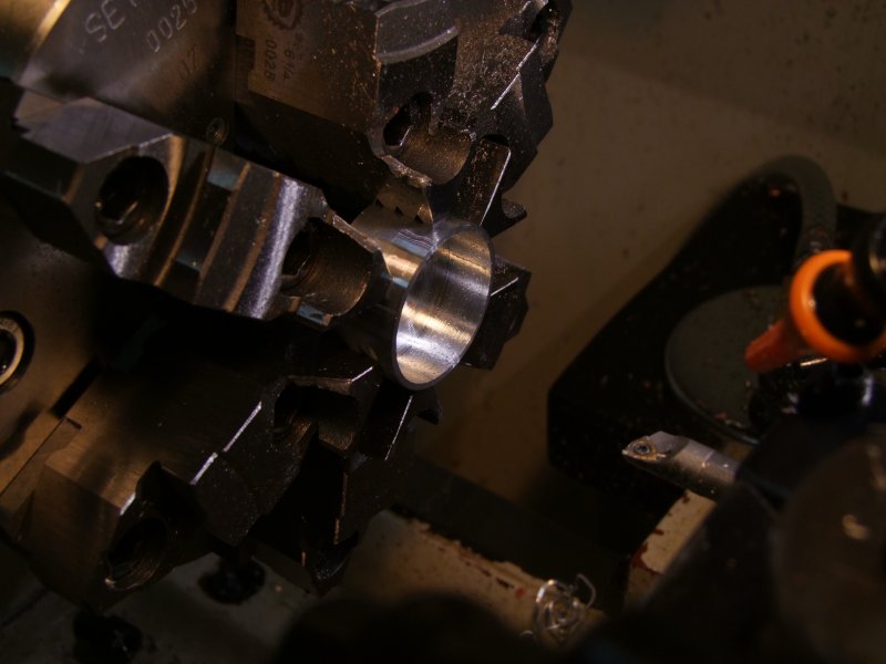
Since this build is modular and it will involve a couple of thermal transfer areas, I decided to use a copper core for the SST-50:
To maximize thermal transfer the piece was lightly sanded, corners smoothed out, etc.:
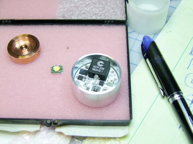
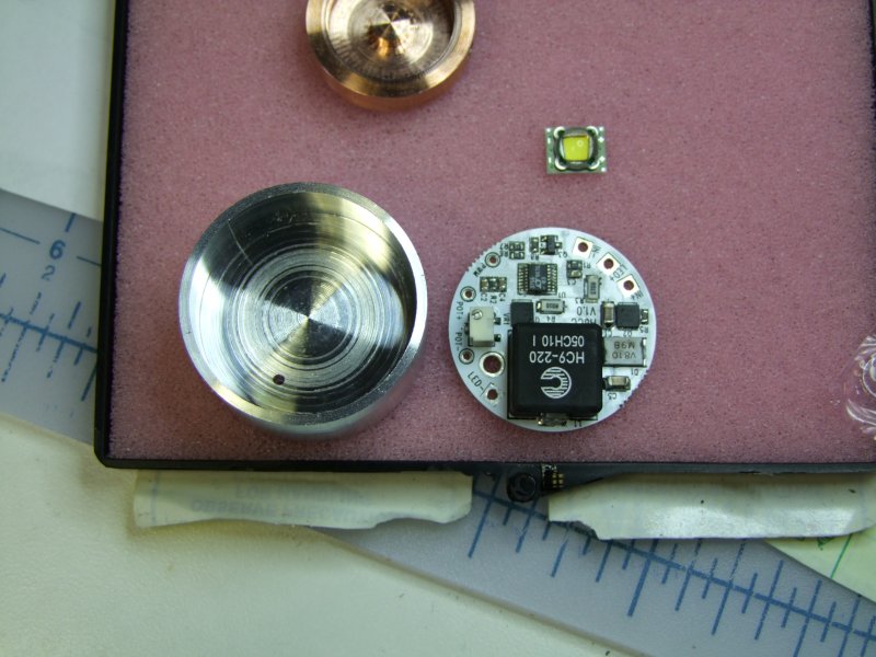
I then started to work on the heatsink/driver "module":
The copper core will be press fit with "thin" thermal paste and keep in place by a hidden set screw:
Again, for best thermal transfer, I decided to flow solder the SST-50 to the copper piece, so I made a small "post" so that I can then solder the wires from the sides:
I then worked on the other side of the module to make room for the H6CC current driver (set conservatively to 5Amps):
Reflow LED:
and test it to make sure I did not kill it:
Solder wires (very hard to solder wires "blind" from the underside!) and then test it at rated current (5A, but do to the long Power Supply wires the voltage was of course higher than the actual vf):
To provide mechanical strength to the solder wires, and so seal the cavity I used 2-part epoxy (even mixed glow in the dark powder for fun, although it is hard to see behind the reflector!):
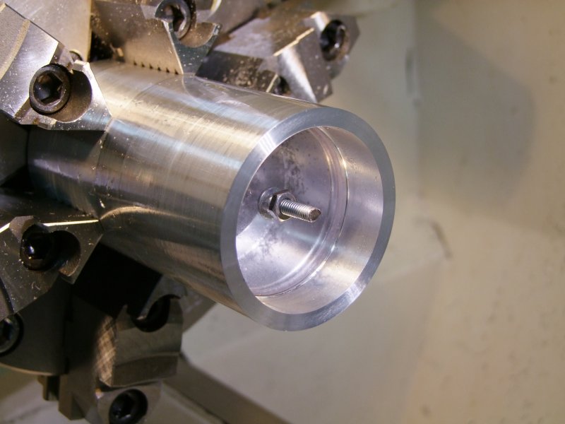
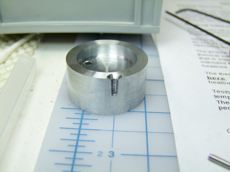
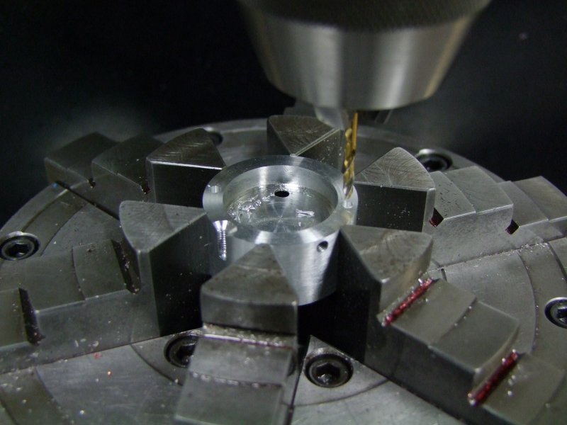
To make 100% of the solid electrical contact for the negative battery, I am using a screw through the head, through the lip of the body - no chance for anything intermittent in a diving light!:
I then milled a relief area for the screw head:
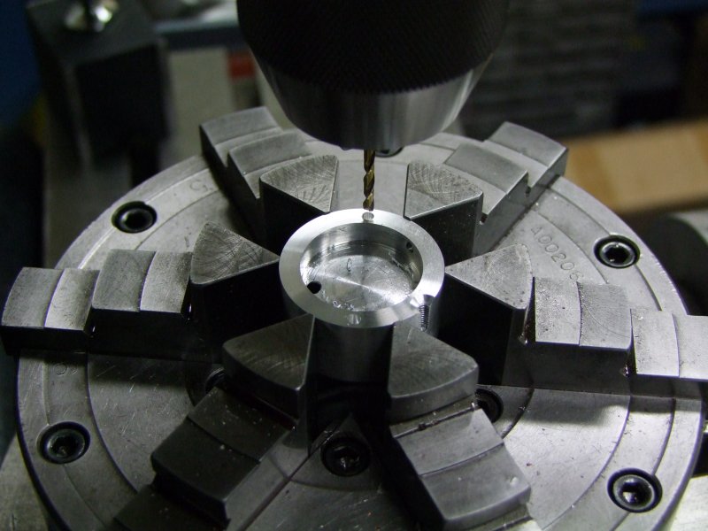
I am also using a screw to keep the LED/driver module firmly in place:
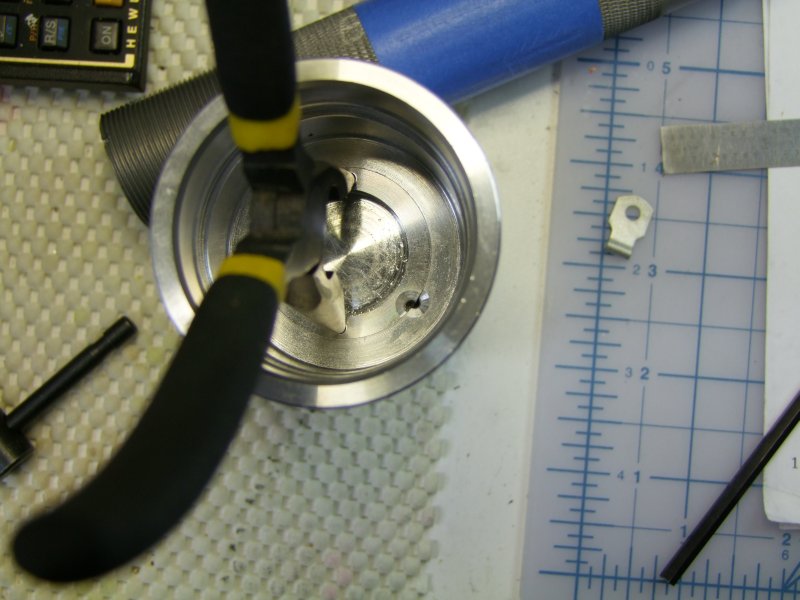
Since it is a slight press fit, I drilled two small holes so that I could use thin nose pliers to align the module with the screw hole:
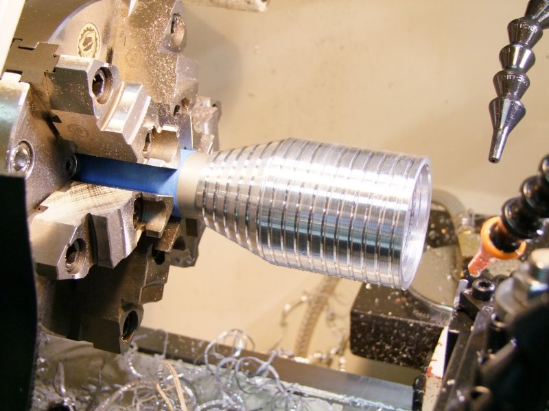
Since I have to trim the length of the head and since the head is too smooth and slippery, I cut some shallow grooves:
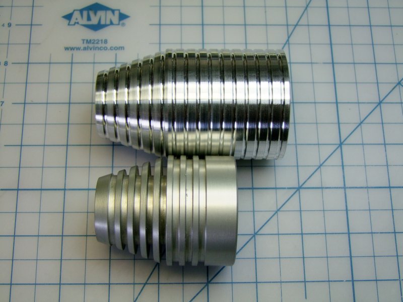
Here is now the finished head, next to the original one. The extra length is for the driver/module/wires/etc.. Is is also much stronger (although heavier) than the original head:
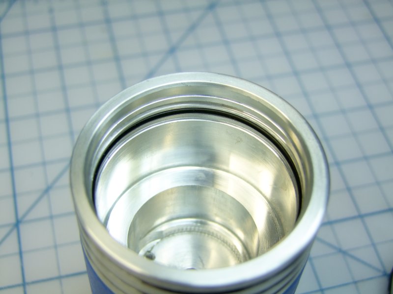
I then did a light boring to fit the "fatty" IRM C cells:
To prepare for powder coating, I bought some silicon plugs (these stand 500+ F, far lower than the 400F needed for the coating to take in the oven):
Unfortunately for the shinny finish, I had to sandblast the surface to aid in the adhesion of the powder coating:
I am using a copper wire through the center to ensure good electrical contact (critical for powder coating):
So after getting parts cleaned and pre-heated (to evaporate any residue):
I then coated them:
I then re-assembled the tailcap:
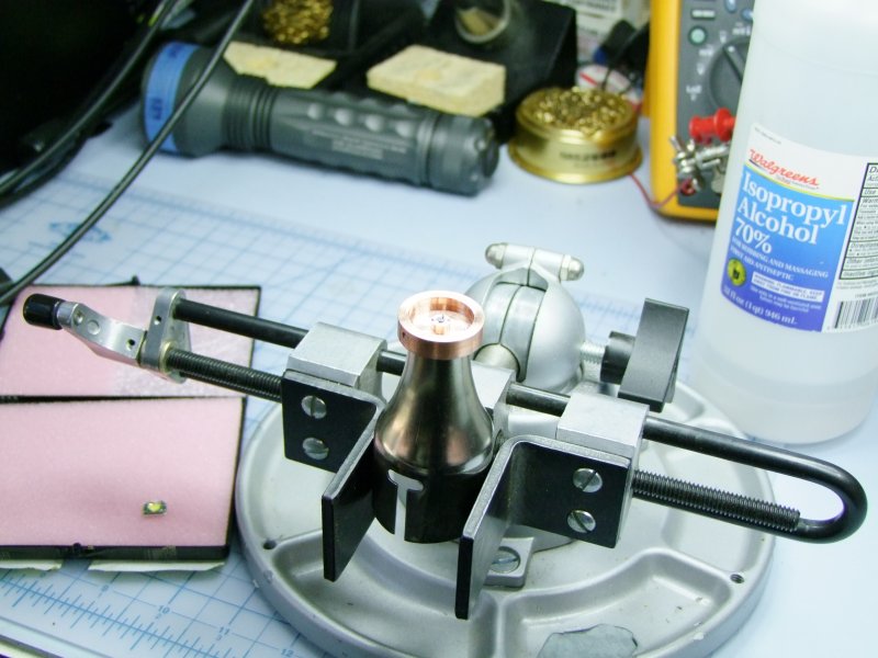
To give you an idea of scale/size:
With the IMR cells, this is how little the spring has to be compressed:
Here I am assembling the copper core to the heatsink module. The fit was so good, that even after applying this thin liquid, it became a press fit:
I then soldered and setup the H6CC to the other side of the module:
I then tested everything again:
I then applied a little epoxy to make sure things stay put:
This is the center conductor to the Bat +:
And this is how the module connects to the Bat - and Bat +:
I did a test fit and test for operation:
And then, with the head not fully screwed in, another test using real IMR cells:
I guess it is a coincidence that the all parts, including the cells are orange!:
I now have to make a custom fitted ring to hold the reflector in place:
I then sanded it for a light sliding fit in the head:
Once I was happy with the fit, I epoxied the centering ring to the reflector:
A coat of Krapton tape to make sure I can't have any shorts with the LED:
Here I am doing the final assembly (blue stuff is Loctite):
Seal the head to the battery tube (had to access sealant from side as top was dry!):
Lightly coat module with thermal paste:
and seat in place (here I am not done cleaning the interior - not that anyone will see this part anyway, but that is the way I am!):
and finally test the beam (unfortunately during bright daylight (see garage door open on left!):
I then took the reflector out, coated the edge with epoxy and glow in the dark powder:
In this photo you can see a "little" bit of the glow around the LED as well:
This o-ring on top of the reflector (once you install the lens) keeps the reflector in place and with zero rattles:
Here is the finished light:
Next to the warm MC-E version I did for the same owner back in January of this year:
I will post some beamshots tonight when it gets dark again
Will
Last edited: