As detailed in this thread, I had gotten a Petzl Tikkina2 for my daughter as she likes to use it during story time right before bed (and another for my sister for the same reason). It's a great little headlamp but not quite suitable for reading as the beam was too narrow, the hue was too blue and even on the lowest setting it was a bit bright for dark adapted eyes. My sister attested as much after using it for about a week and shelved it in favor of my bro-in-law's LL H7 due to the low floody beam.
After doing a little reading in the LED forum, I found a thread disucssing the Radio Shack 276-0017 5mm LED (hereon just RS) and decided to grab some to modify this headlight.
I was initially a little concerned about the donut hole this LED produces (details in the linked thread above) but couldn't be happier with the end result (Bolster, I think you're gonna like this one too but it likely won't qualify for your flood list since this is a mod).
Given I didn't have a lot of time for documentation, here are the annotated steps:
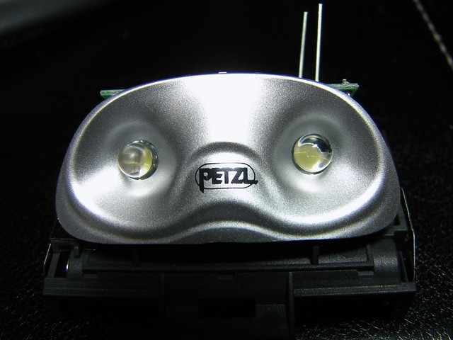
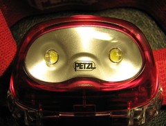
After removing the two T5 torx screws, I removed the main module. Here's a front and top shot:
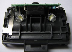
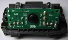
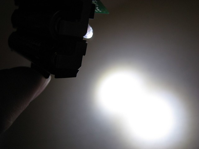
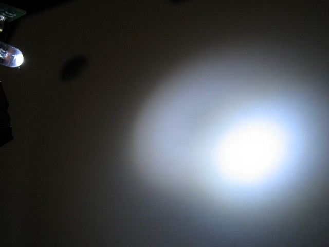
And a pre-mod beamshot as reference:
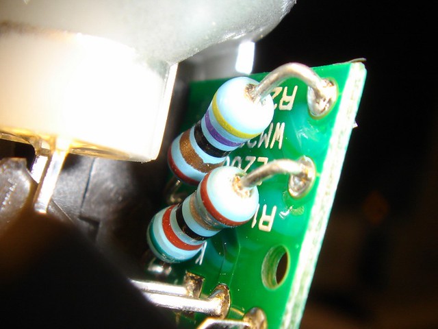
Removing the original LED and putting it back in is perhaps the trickiest part of this mod given there isn't too much room to work with. Once I removed the right LED, I used desoldering braid to clean up the excess solder to make insertion of the RS easier:
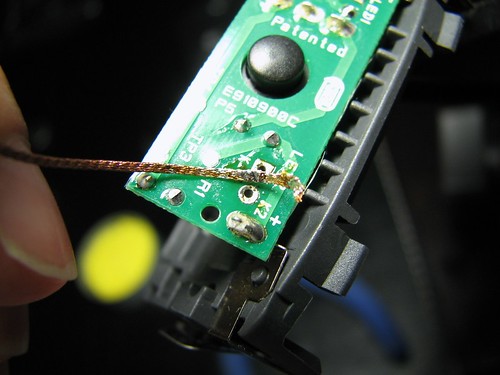
(I must confess that in my younger (and less wiser/patient) days, I would've forgone this step which would have made this mod a lot harder).
I used the faceplate as a LED holder to ensure that I soldered on the RS at the correct angle and depth, the RS is slightly larger and fits into the faceplate snugly. As a result of this, I noticed that the beam was spot on w/out any adjustment necessary as initally the original LED's (which are a bit smaller) were slightly misaligned causing an imperfect beam when projecting onto nearby items/walls.
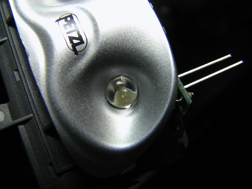
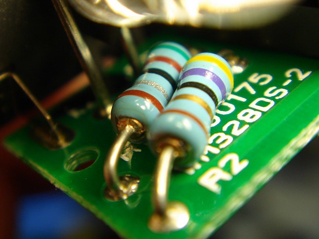
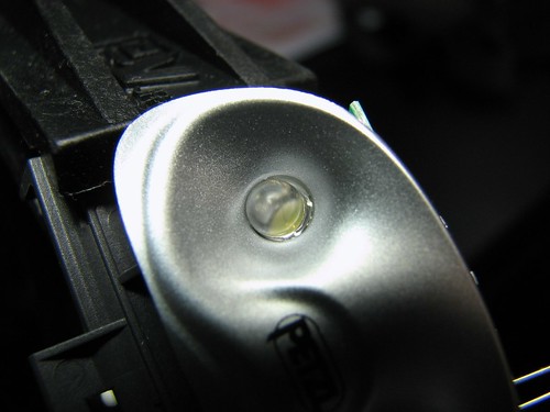
Here's the original LED, notice the slight gaps around it:
And a side-by-side comparo shot:
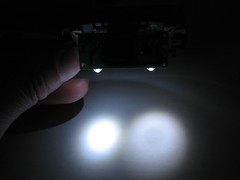
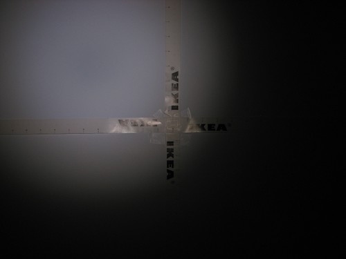
And a comparo beamshot after I repleced one LED w/the RS one:
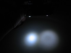
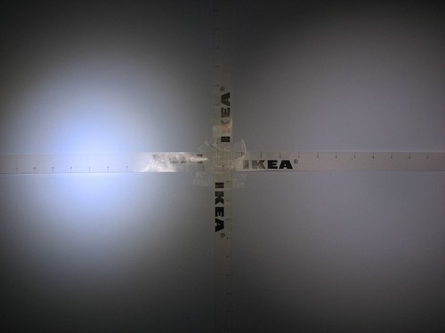
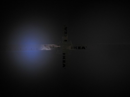
Additional comparo beamshots (right shot stepped down to emphasize donut hole):
It looked pretty good so I wrapped up the rest of the upgrade and put it all back together.
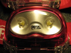
Umodded and modded comparo:
And now the moment of truth, comparo beamshot (L to R: unmodded, modded, H31w):
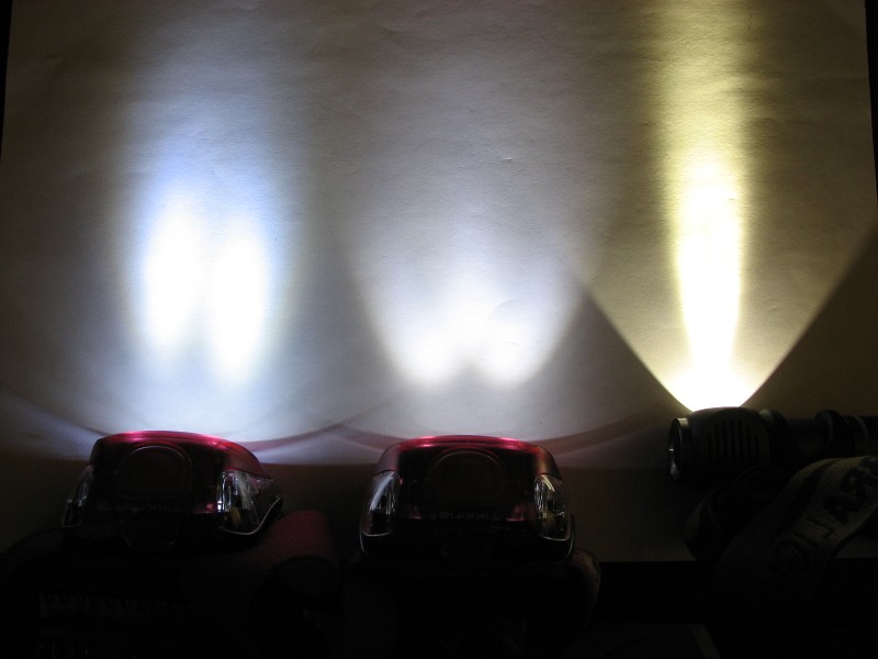
Check out that nice neutral tint!

And of course the requisite beamshot on the wall (pure flood baby but w/very subtle donut hole):
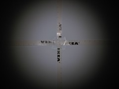
Shifted to the top-left to emphasize donut hole:
And some Side-by-side w/unmodded Tikkina2 (bottom shot stepped down):
Due to the floody beam of the RS, it lost a bit in throw but again I'm very happy w/the results. Here are the specs between the two:

(Throw & Beam width in inches, Angle in degrees, X = Angle/Beam)
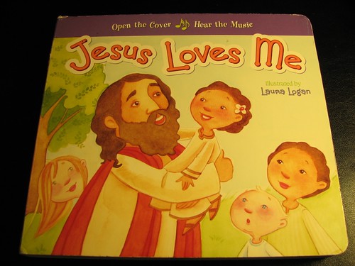
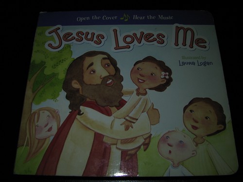
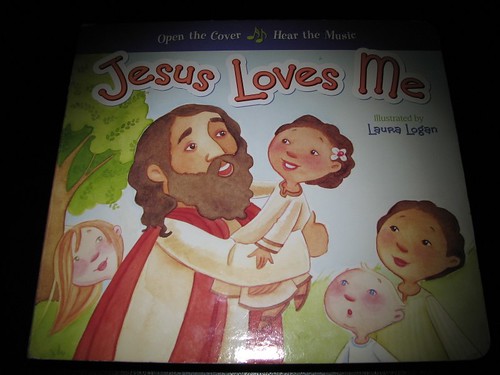
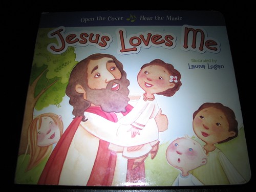
So how's it in real world use? Here are some comparo shots of my daughter's favorite book lit by various sources.
Reference shot under Fluorescent (1/25 f2.7, Daylight WB, slightly warmer than what my eyes see):
Gen1 H501 on Low:
Tikkina2 Neutral Flood Mod:
Tikkina2 unmodded:
And last but not least, some comparo shots between the RS (left) and original LED (right):
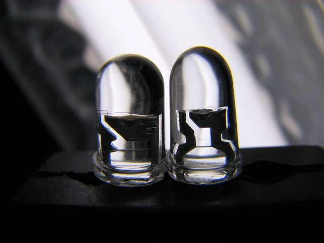
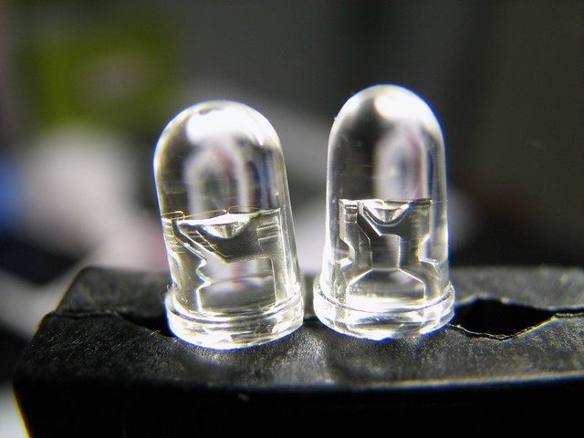
Notice how the original seems to taper off towards the tip, perhpas this enhances the throw? Not sure exactly how the dome shape affects the beam but it would be nice if there was a program that could help you calculate that.
Anyways, hoped you guys enjoyed this little mod. I'll try to get some additional beamshots later next week.
Cheers,
Tim
After doing a little reading in the LED forum, I found a thread disucssing the Radio Shack 276-0017 5mm LED (hereon just RS) and decided to grab some to modify this headlight.
I was initially a little concerned about the donut hole this LED produces (details in the linked thread above) but couldn't be happier with the end result (Bolster, I think you're gonna like this one too but it likely won't qualify for your flood list since this is a mod).
Given I didn't have a lot of time for documentation, here are the annotated steps:
After removing the two T5 torx screws, I removed the main module. Here's a front and top shot:
And a pre-mod beamshot as reference:
Removing the original LED and putting it back in is perhaps the trickiest part of this mod given there isn't too much room to work with. Once I removed the right LED, I used desoldering braid to clean up the excess solder to make insertion of the RS easier:
(I must confess that in my younger (and less wiser/patient) days, I would've forgone this step which would have made this mod a lot harder).
I used the faceplate as a LED holder to ensure that I soldered on the RS at the correct angle and depth, the RS is slightly larger and fits into the faceplate snugly. As a result of this, I noticed that the beam was spot on w/out any adjustment necessary as initally the original LED's (which are a bit smaller) were slightly misaligned causing an imperfect beam when projecting onto nearby items/walls.
Here's the original LED, notice the slight gaps around it:
And a side-by-side comparo shot:
And a comparo beamshot after I repleced one LED w/the RS one:
Additional comparo beamshots (right shot stepped down to emphasize donut hole):
It looked pretty good so I wrapped up the rest of the upgrade and put it all back together.
Umodded and modded comparo:
And now the moment of truth, comparo beamshot (L to R: unmodded, modded, H31w):
Check out that nice neutral tint!
And of course the requisite beamshot on the wall (pure flood baby but w/very subtle donut hole):
Shifted to the top-left to emphasize donut hole:
And some Side-by-side w/unmodded Tikkina2 (bottom shot stepped down):
Due to the floody beam of the RS, it lost a bit in throw but again I'm very happy w/the results. Here are the specs between the two:
(Throw & Beam width in inches, Angle in degrees, X = Angle/Beam)
So how's it in real world use? Here are some comparo shots of my daughter's favorite book lit by various sources.
Reference shot under Fluorescent (1/25 f2.7, Daylight WB, slightly warmer than what my eyes see):
Gen1 H501 on Low:
Tikkina2 Neutral Flood Mod:
Tikkina2 unmodded:
And last but not least, some comparo shots between the RS (left) and original LED (right):
Notice how the original seems to taper off towards the tip, perhpas this enhances the throw? Not sure exactly how the dome shape affects the beam but it would be nice if there was a program that could help you calculate that.
Anyways, hoped you guys enjoyed this little mod. I'll try to get some additional beamshots later next week.
Cheers,
Tim
Last edited: