need help: locate specific resistor on driver board

sl33pyriceboi

Newly Enlightened
Joined
Aug 16, 2009
Messages
30
hello guys. i need some help. i hope i posted in the correct forum. if i didnt i apologize.

so here is my situation, i bought these drivers from DX http://www.dealextreme.com/p/18v-5w-cree-circuit-board-for-flashlights-16-8mm-5-5mm-26110 to power my XM-L led for a custom turn signal led for my car.


on one of the reviews it says:

"If you change the sense resistor to 0.125 ohm, the output current is changed to 2A (the AX2002 has 0.25V feedback voltage)."


my question is, where is the resistor that i will need to be replaced? i dont know where the "sense resistor" is.

here is a pix of the driver board. any help will be appreciated.

thanks CPF community

26110-ecfe558a-1d81-453f-9d87-f75f53a150f3.jpg

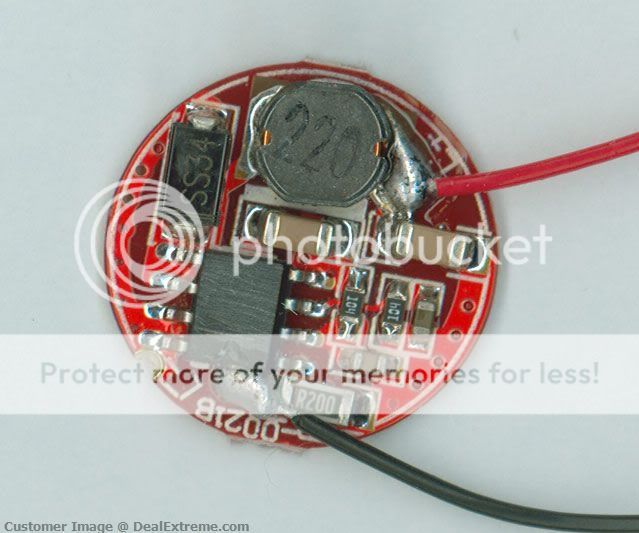
(image borrowed from DX)
 

Justin Case

Flashlight Enthusiast
Joined
Mar 19, 2008
Messages
3,797
It's the resistor marked R22 next to the big solder blob where the black LED- wire is connected.
 

Microa

Enlightened
Joined
Mar 10, 2011
Messages
256
Location
Hong Kong
If you change the output current to 2A, you should consider A) the inductor (Coil) of this size (0504) which Max Idc is 1.0A-1.5A for 22uH. B) the common type 1206 chip resister is rated 0.25W. The power dissipation of the resistor is 0.5W. You should stack 3 pieces of 0.39 to make 0.13 ohm. C)without adequate cooling the driver will be very hot and over heat shut down.
 
Last edited:

sl33pyriceboi

Newly Enlightened
Joined
Aug 16, 2009
Messages
30
If you change the output current to 2A, you should consider A) the inductor (Coil) of this size (0504) which Max Idc is 1.0A-1.5A. B) the common type 1206 chip resister is rated 0.25W. The power dissipation of the resistor is 0.5W. You should stack 3 pieces of 0.39 to make 0.13 ohm. C)without adequate cooling the driver will be very hot and over heat shut down.

*scratches head* that all sounds like quantum physics. please pardon my ignorance/stupidity =[

i think i kind of understood it.

but i dont quite understand B. when you said "stack 3 pc of .039 to make .13 ohm)

1. what is .039? is that a resistor?
2. when you say stack, do u mean solder them as a parallel or in a sequence?


part C... i will only be using this for a car turn signal application. the led/driver will be only momentarily working for a few sec... could this still generate that much heat to possibility shut off the driver?
 
Last edited:

sl33pyriceboi

Newly Enlightened
Joined
Aug 16, 2009
Messages
30
ok ok ok. i have an idea guys but i dont knwo if it will work...

since each driver puts out aprox 1A (it has varied from 1-1.3A), could i run TWO drivers in parallel into my XM-L? would that put about 2A into the LED?

(ive seen guys in the DIY forum stacking drivers in parallel)
 

sl33pyriceboi

Newly Enlightened
Joined
Aug 16, 2009
Messages
30
dedicated turn signal. the led/driver will only be activated when i use the turn signal.
 

Justin Case

Flashlight Enthusiast
Joined
Mar 19, 2008
Messages
3,797
did you mean the "R200" ???

In the DX link, it looked like an R22 (I'm limited to a low res image). If it's R200, then fine. I think it's pretty clear there is only one candidate resistor in the location descibed, regardless of marking.
 

sl33pyriceboi

Newly Enlightened
Joined
Aug 16, 2009
Messages
30
In the DX link, it looked like an R22 (I'm limited to a low res image). If it's R200, then fine. I think it's pretty clear there is only one candidate resistor in the location descibed, regardless of marking.

ok. thanks. i wasnt sure. i appreciate the help very much.
 

Microa

Enlightened
Joined
Mar 10, 2011
Messages
256
Location
Hong Kong
You need a 0.125 ohm sense resistor for 2A current output. Three 0.39 ohm resistors are connected in parallel which equivalent to the value 0.13 ohm, close to the value 0.125 ohm. The rated watt capacity will be 3 x 0.25W = 0.75W.
 

xul

Enlightened
Joined
Aug 28, 2011
Messages
336
Location
MD
#30 wire wrap wire is about 10' per ohm and it fuses at 8 to 10A; sometimes this comes in handy for making low ohm resistors.
To measure it use a four terminal Kelvin method. Pass a current of 2A or so through the wire and measure the voltage drop across a length of the wire. The voltage sense leads should not touch the terminals that pass the current.
 
Last edited:

Microa

Enlightened
Joined
Mar 10, 2011
Messages
256
Location
Hong Kong
The link is a 5W wire wound resistor too big for the driver board. 1206 size chip resistor is 3.1mm x 1.6mm.
 

Justin Case

Flashlight Enthusiast
Joined
Mar 19, 2008
Messages
3,797
Check Digikey for 1/2 watt 1206 current sense resistors with the desired resistance. Stackpole and Vishay-Dale should have the appropriate products. There is probably no need to use parallel sense resistors, which adds more hassle in soldering.
 

Microa

Enlightened
Joined
Mar 10, 2011
Messages
256
Location
Hong Kong
The power applied on the resistor is 0.25V x 0.25V / 0.125R = 0.5W. You should add some safty margin. A 0.75W to 1W resistor should be appropriated.
 

Justin Case

Flashlight Enthusiast
Joined
Mar 19, 2008
Messages
3,797
I should have been clearer in that there is probably no need to go with stacked, parallel resistors.

If the DX26110 is like the DX3256 and KD1640, with two sets of solder pads for two sense resistors in parallel, then I'd get two 0.25 ohm 1/2W current sense resistors from Digikey as described before. I'd de-solder the stock sense resistor and solder in the two 0.25 ohm resistors. If the 26110 driver doesn't use a second set of solder pads, then I'd probably get the DX3256 driver instead. Last I've seen anyway, the 3256 also uses the AX2002 buck IC (even though the DX web site says it uses a C310). A hangup is that the 3256 uses a 1A rated SS14 diode, which also would need to be changed.
 
Top