Got Lumens?
Flashlight Enthusiast
Hi,
I am a 4 Sevens fan and customer. I have been reading the other thread avidly. Many have said that the 4 Sevens newly release Preon0 is incompatable with eneloop batteries. Below are two videos from the first run of Preon0's.
UPDATE:The Preon0 has been updated to V1.2! The current and future shipments are a new version 1.2 of the light which addresses and corrects all observations noted here in this thread of the first run and releases. See post#18
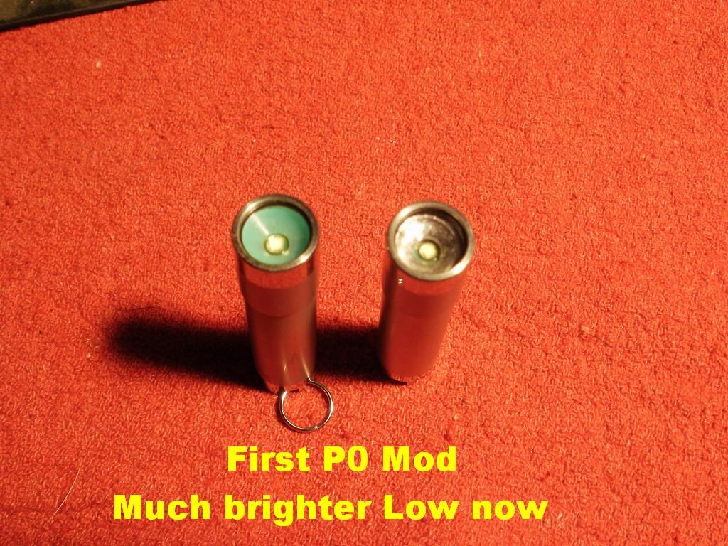
The first video is a first hand look at a Preon0 out of the package. I have used eneloops in the second Preon0 in the video without problems(see post#5 CORRECTED). One by removing the foam completely, and second by opening up the center hole in the foam using a 3/32" center punch. I have heard that Lithium AAA cells function well also. I really like the light. I would like the magnet to be removeable, but it actually serves as the force to keep the battery from rattling. The GITD feature works for me. Could it be better? My answer is yes, by using a GITD o-ring between the head and lens of the light and replacing the GITD plastic with plastic that utilizes GITD paint instead. Ex. If a GITD white paint were used, it would reflect white and not green. I must admit that these shaded tints were only noticable in the very outer edges of the beam(whitewall hunting:huh") , and not within the beam on my two samples. I would like to see 3 levels, the existing Firefly, a higher low ~2-3lm, and the existing high(a few more lumens wouldn't hurt). Overall I am satisfied with the quality of build, I like the beadblasted finish, and absolutely love it's size. :thumbsup:
, and not within the beam on my two samples. I would like to see 3 levels, the existing Firefly, a higher low ~2-3lm, and the existing high(a few more lumens wouldn't hurt). Overall I am satisfied with the quality of build, I like the beadblasted finish, and absolutely love it's size. :thumbsup:

4 Sevens Preon0 Video Mini-Review
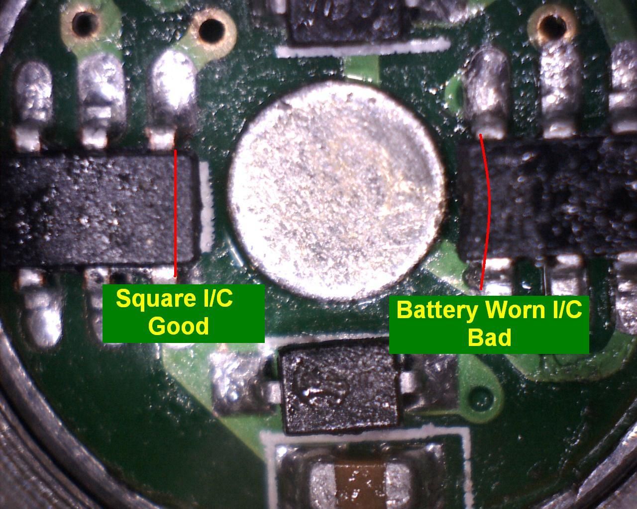
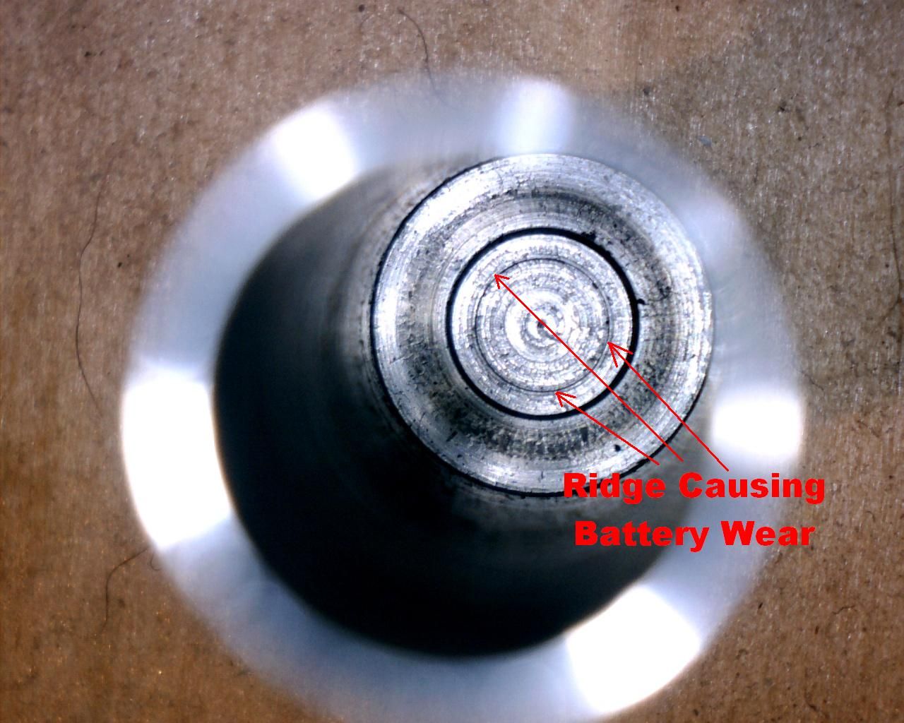
Many have questioned whether the Preon0 is damaging itself or the batteries. I do not beleive that is the case, unless you are using enough twisting force to litterally crush the battery. The second Video has no audio and shows that the Preon0 components protrude ~0.5mm or less upward from the driver board. The foam spacer is ~2.2mm thick, can be compressed to about ~0.41 mm, and most importantly that both Duracells and Eneloops are flush with the Preon0 endtube, and both positive contacts protrude by atleast ~1.37mm. Given these tollerances and the ~1mm clearance using both batteries, I beleive the main problem is in the foam inserts design. Due to the eneloops square shaped button, I believe that it is pinching the foam between it and the driver. I have seen particles of foam and them getting lodged within the threads of the head and body. This maybe from the endtube tearing at it, not sure. I clean my lights regularly, I will use the second Preon0 and update this post if necessary. Update coming soon . . . see post#5. CORRECTED in V1.2

4 Sevens Preon0 Video Battery Compatibility Corrected in V1.2
There have been nine updates and changes to the Preon0 v.1.2 . Here's my new Change Video:

GL
Got Lumens?
I am a 4 Sevens fan and customer. I have been reading the other thread avidly. Many have said that the 4 Sevens newly release Preon0 is incompatable with eneloop batteries. Below are two videos from the first run of Preon0's.
UPDATE:The Preon0 has been updated to V1.2! The current and future shipments are a new version 1.2 of the light which addresses and corrects all observations noted here in this thread of the first run and releases. See post#18
The first video is a first hand look at a Preon0 out of the package. I have used eneloops in the second Preon0 in the video without problems(see post#5 CORRECTED). One by removing the foam completely, and second by opening up the center hole in the foam using a 3/32" center punch. I have heard that Lithium AAA cells function well also. I really like the light. I would like the magnet to be removeable, but it actually serves as the force to keep the battery from rattling. The GITD feature works for me. Could it be better? My answer is yes, by using a GITD o-ring between the head and lens of the light and replacing the GITD plastic with plastic that utilizes GITD paint instead. Ex. If a GITD white paint were used, it would reflect white and not green. I must admit that these shaded tints were only noticable in the very outer edges of the beam(whitewall hunting:huh
, and not within the beam on my two samples. I would like to see 3 levels, the existing Firefly, a higher low ~2-3lm, and the existing high(a few more lumens wouldn't hurt). Overall I am satisfied with the quality of build, I like the beadblasted finish, and absolutely love it's size. :thumbsup:4 Sevens Preon0 Video Mini-Review
Many have questioned whether the Preon0 is damaging itself or the batteries. I do not beleive that is the case, unless you are using enough twisting force to litterally crush the battery. The second Video has no audio and shows that the Preon0 components protrude ~0.5mm or less upward from the driver board. The foam spacer is ~2.2mm thick, can be compressed to about ~0.41 mm, and most importantly that both Duracells and Eneloops are flush with the Preon0 endtube, and both positive contacts protrude by atleast ~1.37mm. Given these tollerances and the ~1mm clearance using both batteries, I beleive the main problem is in the foam inserts design. Due to the eneloops square shaped button, I believe that it is pinching the foam between it and the driver. I have seen particles of foam and them getting lodged within the threads of the head and body. This maybe from the endtube tearing at it, not sure. I clean my lights regularly, I will use the second Preon0 and update this post if necessary. Update coming soon . . . see post#5. CORRECTED in V1.2
4 Sevens Preon0 Video Battery Compatibility Corrected in V1.2
There have been nine updates and changes to the Preon0 v.1.2 . Here's my new Change Video:
GL
Got Lumens?
Last edited:

 , other are not like the one I have and yours