A couple Mag mods, with modded SB drivers.

brandocommando

Enlightened
Joined
Mar 10, 2011
Messages
437
Location
Oregon
Here are my (first) 2 recent Maglight projects. They are both powered with 8000mAh Tenergy Centura LSD NiMh D cells.

The first one is a brand new 3 D, I went out and bought just for modding. It has:

H22A heatsink
U2 (1C) XM-L on a 20mm star
DX glass lens
2.8A SB driver modded with 4 additional AMC 7135 chips
Stock reflector (modded)
Stock switch (modded)

001.jpg

007.jpg

006.jpg

012-1.jpg

012.jpg


This total set-up cost around $50! It is set up for L/M/H operation, and it works fantastic. It has momentary activation, and I can change modes with a simple soft press. It is very bright, and has a really nice beam. I used Arctic Alumina Thermal Adhesive to mount the LED and the driver, and some Arctic Silver 5 thermal paste around the heatsink. I was hoping for around 4A on this one, but with only 3 D batteries I am getting only around 3.3A. I tested it with 4 cells and it went up to 3.9A. Should have gone with a 4 D I guess, but I can live with it. I like the smaller size of the 3 D, and 3.3A is still pretty good! This Maglight still surprised me when I took it outside for the first time, it has GREAT throw! I went the cheap route on this one and am just using the stock reflector. It was easy to cut, and was all I could figure out for use with that big 20mm star. I got lucky, this combo actually works great when properly focused, which is easy, because the cut out in the reflector fits around the outside of star allowing full travel.


The second one is a VERY old 4 D Maglight I have had since I was a kid. After being bit by the flashlight bug, it was killing me having this useless old light collecting dust. I had to do something to save it from the trash heap! I bought a bunch of parts from another CPF member and put this together. I couldn't decide on a driver to use for the SST-90 at first. I knew I wanted multiple modes, so I eventually decided to just use another 2.8A SB driver... I have been pretty successful modding them in the past, as I have built several 4.2A p60 modules. I decided I was going to really go for it with this one... It has:

BrightLumens SST-90 heatsink
De-domed SST-90 (unknown bin)
DX glass lens
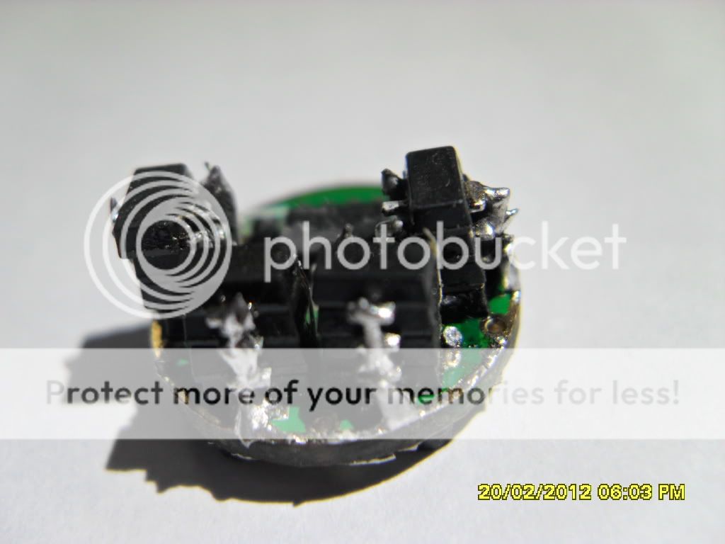
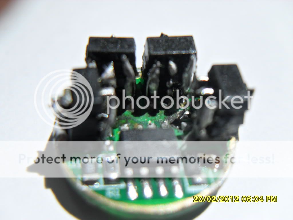
2.8A SB driver modded with 16 additional AMC 7135 chips!:eek:
BrightLumens 17mm aluminum OP reflector
Stock switch (modded)

013.jpg

016-6.jpg

026-3.jpg

022-4.jpg

031.jpg

033.jpg


I am not sure, but I would say that this one cost less then $100. I got the SST-90, the reflector, and the heatsink for around $50, on CPFMP.
It wasn't easy modding the driver, but it fired right up the first time! It is also set up for L/M/H operation. I guess I have gotten pretty good at soldering those chips! There are 3 chips stacked all around on one side, and 3 chips stacked all around on the other side. A total of 24 chips! It also has momentary activation, and I can change modes with a simple soft press. It is very, very bright, and has a really nice beam. I used Arctic Alumina Thermal Adhesive to mount the LED and the driver, and some Arctic Silver 5 thermal paste around the heatsink. I was hoping for around 8A on this one, and with the 4 D cells I came pretty close! It does not throw quite as well as the 3 D XM-L, but it's not too bad either! This one is also focus-able (obviously.)

I will be building an aspheric Maglight next, just waiting on some parts to arrive... Stay tuned!
 
Last edited:

brandocommando

Enlightened
Joined
Mar 10, 2011
Messages
437
Location
Oregon
Ummm... Nothing!

Ha Ha, thanks.
What I do is, solder the big back tabs first, and just hold it down with a little screwdriver, (or my finger.) Then, once the back is secure, I can work on the front 3 tabs without worrying about any further movement...

I went around and did the first layer/level, adding 1 chip on top of every chip already on the board. At this point I had 8 chips added. THEN, I went around a second time and using the same process, added ANOTHER level (8 more chips) all the way around!

Basically, I just did it one chip at a time.

I grew up in Omaha (Papillion) actually... Lived there for almost 20 years!
 
Last edited:

Quest4fire

Enlightened
Joined
Aug 13, 2006
Messages
287
Location
Nebraska
I applaud your soldering skills 'cause by the time I got that many chips tacked down I'd be ready to spit nails! I'm not from Omaha originally (Gulf coast) but I have enjoyed living here.
 

brandocommando

Enlightened
Joined
Mar 10, 2011
Messages
437
Location
Oregon
Yeah, you got to be patient for sure. Not a job you want to rush...

I couldn't believe it when I finally got it all put together (and it worked) and I got 8A at the tailcap. I was pretty happy.:)

Not bad for a $7 driver, and $8 worth of chips!
 

Mattaus

Flashlight Enthusiast
Joined
Mar 29, 2011
Messages
1,765
Location
Brisbane, Australia
How long does it run at the full 8A for? I'm guessing you would notice some current sag (or whatever the right term is) after the chips get a bit hot?
 

hellokitty[hk]

Enlightened
Joined
Jan 29, 2007
Messages
645
How long does it run at the full 8A for? I'm guessing you would notice some current sag (or whatever the right term is) after the chips get a bit hot?
I'd bet that he's getting more than 8A when it doesn't have to go through the multimeter and its leads.
 

brandocommando

Enlightened
Joined
Mar 10, 2011
Messages
437
Location
Oregon
Well there are 24 / 350mAh chips total. If you do the math, then that should be 8.4A total. I get about 8.3A right at turn on and then it drops a little, to around 8.2A - 8A. I have a nice multimeter, but the leads are a pretty long...

I could have just went direct drive I suppose, but I really like multi-mode lights. I like having the regulated 8A on high also.

I have not done a runtime test yet, but they are 8000mAh batteries. I doubt it would run at the full 8A for an hour, the cells would be pretty dead by then.

I don't know about the chips getting hot either, I have never checked on their tempurature!
 
Last edited:

Mattaus

Flashlight Enthusiast
Joined
Mar 29, 2011
Messages
1,765
Location
Brisbane, Australia
Well there are 24 / 350mAh chips total. If you do the math, then that should be 8.4A total. I get about 8.3A right at turn on and then it drops a little, to around 8.2A - 8A. I have a nice multimeter, but the leads are a pretty long...

I could have just went direct drive I suppose, but I really like multi-mode lights. I like having the regulated 8A on high also.

I have not done a runtime test yet, but they are 8000mAh batteries. I doubt it would run at the full 8A for an hour, the cells would be pretty dead by then.

I don't know about the chips getting hot either, I have never checked on their tempurature!

Thanks for the reply. I'm looking at making some custom drivers based on the same method you have used, and I was worried about heat sinking the stacked ICs. I am however only going to stack the ICs 2 high at most, and on one side of the board only. It seems heat sinking won't be an issue!!!
 

hellokitty[hk]

Enlightened
Joined
Jan 29, 2007
Messages
645
Well there are 24 / 350mAh chips total. If you do the math, then that should be 8.4A total. I get about 8.3A right at turn on and then it drops a little, to around 8.2A - 8A. I have a nice multimeter, but the leads are a pretty long...

I could have just went direct drive I suppose, but I really like multi-mode lights. I like having the regulated 8A on high also.

I have not done a runtime test yet, but they are 8000mAh batteries. I doubt it would run at the full 8A for an hour, the cells would be pretty dead by then.

I don't know about the chips getting hot either, I have never checked on their tempurature!
Indeed that fluke is not cheap :)
But also consider the contact resistance of the lead tips, and any multimeter will have some resistance, especially as it approaches full scale.
Due to the slope of the vf vs current graph, a tiny change in the voltage at the emitter can have some pretty big effects to the amperages.
Also if you read the datasheets, the SST-90 has a negative vf to temperature coefficient, meaning the vf will get lower as it heats up. If I remember, it's about 1 mv per 2.45 degrees, so the current will probably increase within the first few minutes.
 

simplec6

Enlightened
Joined
Jun 17, 2010
Messages
278
Any tips on stacking the 7135's? Also, you do know if you do the big one on the back, you don't need the center one on the 3-pin side right?
What soldering iron and tip and type of solder?
 

brandocommando

Enlightened
Joined
Mar 10, 2011
Messages
437
Location
Oregon
Indeed that fluke is not cheap :)
But also consider the contact resistance of the lead tips, and any multimeter will have some resistance, especially as it approaches full scale.
Due to the slope of the vf vs current graph, a tiny change in the voltage at the emitter can have some pretty big effects to the amperages.
Also if you read the datasheets, the SST-90 has a negative vf to temperature coefficient, meaning the vf will get lower as it heats up. If I remember, it's about 1 mv per 2.45 degrees, so the current will probably increase within the first few minutes.

Thank you for the info HK, I did not know that about the negative vf of the SST-90!

Any tips on stacking the 7135's? Also, you do know if you do the big one on the back, you don't need the center one on the 3-pin side right?
What soldering iron and tip and type of solder?

Yes, I knew that about the center pin. If you look at the bottom of one of the chips it is obvious they are one and the same....

I figured it makes for that much better of a ground path, and it's good practice to just do all of them I guess!!! :)

I use a very basic 25W Weller that you can get anywhere. I use 60% tin 40% lead "fine electrical solder" (the skinny stuff.)

One trick I found is to snip off some really small bits of solder with some wire cutters. That way you can just use a controlled amount. (Just pick it up with the iron.) When you try to melt it off of the reel you can't always control how much solder you get, (and you will usually get way too much!) Soldering these pins takes just a micro amount of solder. In fact, if your alignment is really good, and pin "bending" is right on, you can do the first level without adding ANY solder, I'VE DONE IT BEFORE!

Also, if you are shakey, you can stick a very small jewlers screwdriver between the pins as a barier while you are working. This can really help in keeping your blob of solder from jumping over to the next pin. Which really sucks BTW...

Also, work in short quick sessions. The entire driver gets really hot when you do this. I have had parts start melting and coming off the board before on the first couple of ones I modded, (when I was still learning how to do this!)
 
Last edited:

vietkhoa

Newly Enlightened
Joined
Apr 10, 2011
Messages
5
Sorry I used google translate for me in Vietnam should not fluent in English.
I also grafted 8x7135 + 12 IC 7135 driver to run the SST-90, but the results failed. I run in parallel 3 18 650 batteries ...
Now let me ask you all as you use the battery box for the star to produce good results as expected ...
This is my driver mod:

SAM_2816.jpg

SAM_2819.jpg
 
Last edited:

brandocommando

Enlightened
Joined
Mar 10, 2011
Messages
437
Location
Oregon
Hi vietkhoa, I am not sure exactly what you are asking about the battery box, could you please rephrase your question?

It looks like you may have gotten the board too hot...

Also, you have to be careful soldering the + and - wires, there is not much room to work with there, and it is pretty easy to short out the + connection.
 

vietkhoa

Newly Enlightened
Joined
Apr 10, 2011
Messages
5
Hi ... I want to ask the driver to power 8x7135 + 16 IC 7135 for the more than 8A.
You have detailed pictures of that power, the better ....
I also have turned this type of gasoline ic transplantation but failed:

3xAMC7135_drivers_stacked_parallel_1-1.jpg
 

Mattaus

Flashlight Enthusiast
Joined
Mar 29, 2011
Messages
1,765
Location
Brisbane, Australia
I shouldn't laugh but Google translate is horrible for long sentences.

All I can say Vietkhoa is try and improve your soldering skills on something else first.

Then try to modify the SB drivers.

Start small and check the driver after each new 7135 is added to see if it's working.

If it works add another.

Keep going until you have the right amount of 7135 chips on there.

I broke that up to make translation easy and hope this translates well into Vietnamese OK.

Hi ... I want to ask the driver to power 8x7135 + 16 IC 7135 for the more than 8A.
You have detailed pictures of that power, the better ....
I also have turned this type of gasoline ic transplantation but failed:

3xAMC7135_drivers_stacked_parallel_1-1.jpg
 

LivingDaylight

Newly Enlightened
Joined
Nov 25, 2011
Messages
70
Probably a n00b question: Isn't the XM-L only rated for 2.8 amps? Wouldn't greater than that do some damage?
 

brandocommando

Enlightened
Joined
Mar 10, 2011
Messages
437
Location
Oregon
They are tough LEDs. They can handle up to 4A and put out 1000 lumens when properly heatsinked.

I think Cree recommends 3A or so...
 

vietkhoa

Newly Enlightened
Joined
Apr 10, 2011
Messages
5
Thanks to everyone for the help, I try to watch star mod. And should I use the battery power of 18650 with (but should transplant sonh How much is it.?)
...
 

brandocommando

Enlightened
Joined
Mar 10, 2011
Messages
437
Location
Oregon
A single 18650 is good for about 4 or 5 Amps. If you want more power than that, I think NiMh batteries are better.

So you have the chip soldering understood OK then?:)


What is the "star mod" you speak of?

I am sorry, I would like to answer you but the translation is not good.:confused:
 
Last edited:
Top