
First of all, a big thanks to those who helped me with this build, either directly in answer to my questions or indirectly by sharing their expertise elsewhere. I recently built this aspherical Maglite mod, and thought that it would be nice to make a step by step guide for the build for other CPF-ers who are interested in a thrower, but wouldn't normally venture into the realm of DIY modding. It's a pretty simple mod that won't set you back much (it ended up costing me under $60), and the end result is something you wouldn't be able to buy very easily. So if you want to try out a ridiculously long-range thrower, you'll need these parts:
So with that established, let's begin the mod! First, pry off the rubber switch cover with a toothpick.
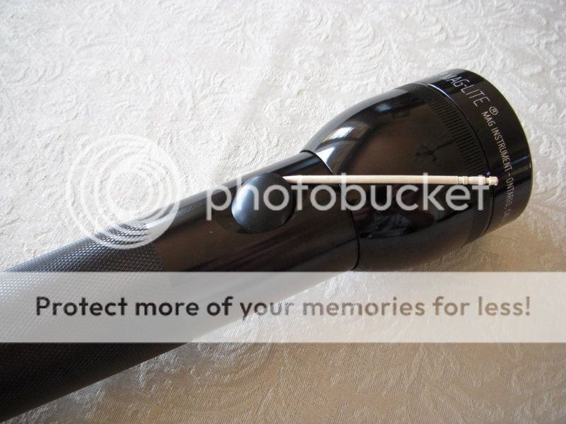
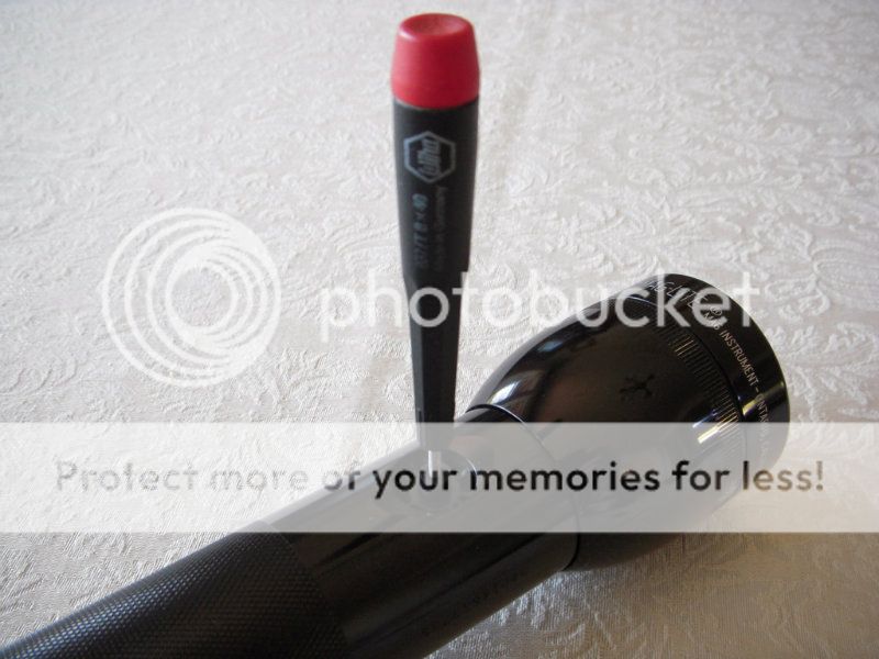
You'll see the switch underneath, which has a hole in the middle that extends to the set screw that keeps the switch in place. Older Maglites only need an allen wrench, but the new ones require a Torx T8 bit. Some of you who collect knives as well may see this as a welcome change, but there's a catch: the hole is not big enough to accommodate a Torx driver shaft, since pretty much every driver out there flares out just past the head. So you'll have to grind the shaft of a Torx T8 bit to get a tool that can disassemble the Mag. I used a Wiha 267, since only minimal grinding is required, and Wiha makes excellent tools (after having a couple cheap hardware store drivers be too off-spec to work or crumble to pieces after weeks, you'll see that the moderate price increase of the Wiha is well justified).
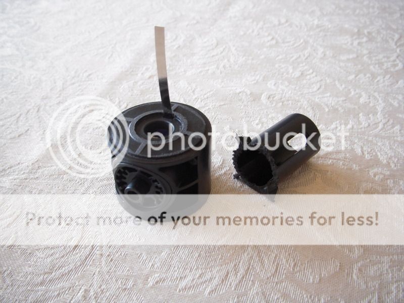
Once you have the set screw unscrewed, you can slide the switch out the tailcap end. Remove the switch and leads from the housing and cut off/sand down the top post. The plastic is soft enough that you don't need power tools. When you put it back together it should look like this.
Cut and sand the reflector down to a small ring, which will hold the lens in place.
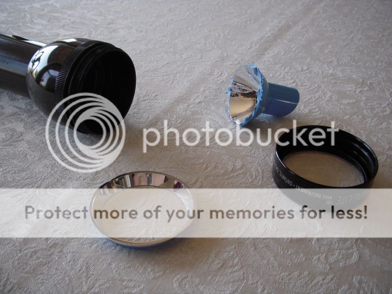
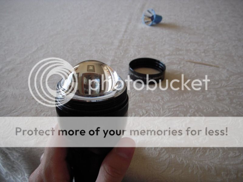
Take out the plastic lens and put in the reflector ring and aspherical lens.
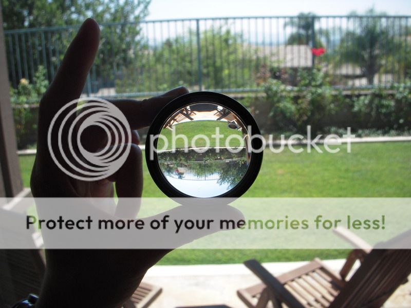
Looks pretty nice, doesn't it? You can test the electronic components now before they're soldered together if you like. A multimeter can test the current the driver delivers, but make sure you wire the multimeter leads in series with the circuit next to the LED, rather than replacing the LED with the multimeter. Otherwise your measurements will be way off.
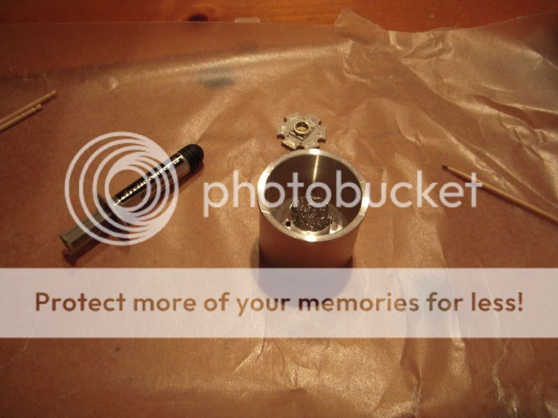
Cover the post of the heat sink with Arctic Silver 5 thermal paste and surround it with a ring of epoxy to secure the LED. Mount the LED on the post, making sure to keep it centered (you can use the lead wire holes as reference points).
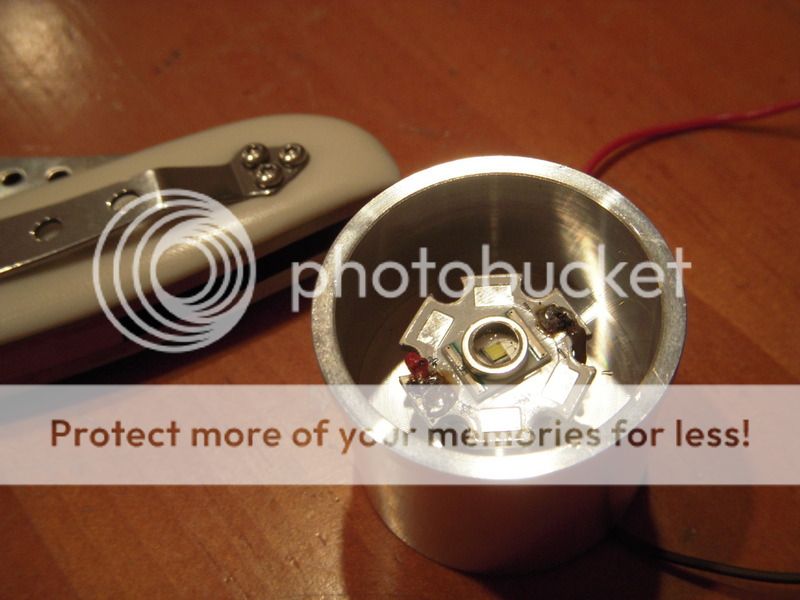
Once the epoxy has cured, solder the lead wires onto the + and – contacts of the LED.
Snip off the long spring from the switch assembly and solder lead wires onto the two contacts in the switch.
Solder the other ends of the LED leads onto the appropriate places on the driver.
Replace the Mag switch and secure the set screw.
Solder the leads from the switch onto the other side of the driver as shown. Be careful not to solder a connection between the outer ring and inner circle contacts.
Attach the driver to the heat sink with Arctic Alumina paste and surround it with some epoxy to secure it into place. Allow it to cure.
Spread a ring of AS5 paste around the base of the heat sink and twist it into the Maglite body, making sure that all of the surface is covered in paste. Apply a ring of epoxy under the heat sink's upper lip and press the parts together. If you want the LED die to be projected in a certain orientation relative to the switch, make sure you have it set that way (keep in mind also that the aspherical lens projects an inverted die).
Keep the heat sink pressed into the body and allow it to cure.
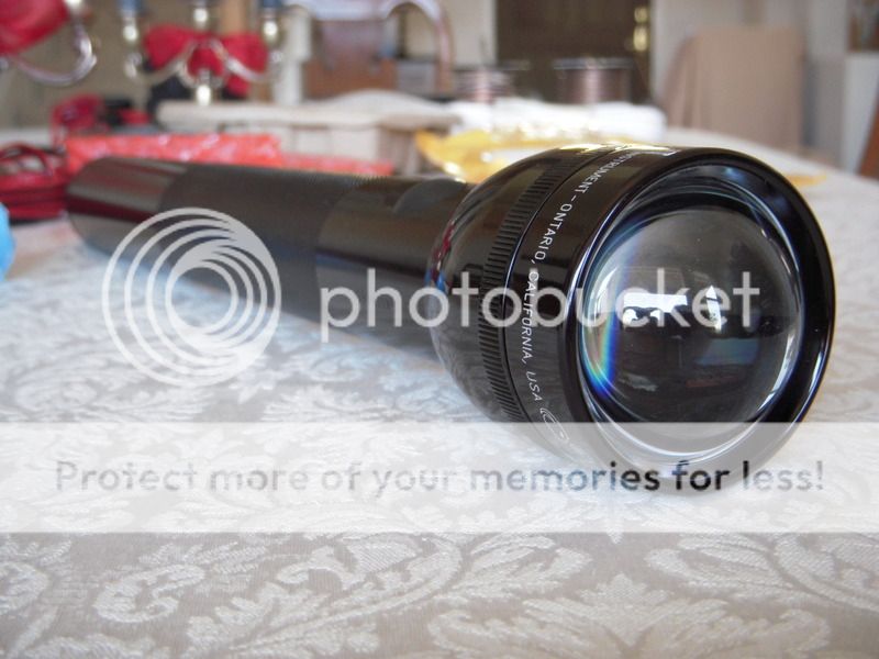
And there it is!
Just put the head back on and you have your light. It looks like a normal Maglite other than the lens, but it most certainly is not.
Here's a weak attempt at a beam shot. The beam is square-shaped, just like the LED. Two of the corners are notched in, where the leads for the emitter are if you look at it really closely. And that beam is CONCENTRATED. It's so tight and bright that I can see the beam in the house (and definitely outside). I'm not sure what the range is, but suffice it to say that it's more than you'll need. Using my binoculars, I can see the light bouncing off objects well over 1000 feet away. Pretty impressive, and definitely something you don't see every day (or rather, night?). Hope you enjoyed the post!

As per my PM.
Your images are too large. Please resize and repost.
See Rule #3 If you post an image in your post, please downsize the image to no larger than 800 x 800 pixels. - Thanks Norm
- A 4D Maglite. The 6V is enough to power the circuit for a decent amount of time while taking into account the voltage drops in the system.
- An aspherical lens from Deal Extreme, SKU 12834. This optic is far cheaper than other options and focuses a tighter hotspot than many other aspherical lenses.
- A 1050mAh LED driver, Deal Extreme SKU 25518. This is a linear, single mode driver that's simple, effective, and reliable (and cheap!).
- A Cree XR-E LED. I used the star-mounted R2, Deal Extreme SKU 15943. Although not the brightest LED out there, the XR-E is well-suited for this purpose because it emits a larger portion of the light straight out the front and into the lens, and the die doesn't have a weird or ugly pattern that will get projected. The star is good for electrically isolating the leads from the heat sink and making them more accessible for soldering.
- H22A heat sink. I was lucky enough to snag the last of his prototype Rebel heat sinks, which mount the LED deeper in the body. The problem with his normal heat sinks for this mod is that the 12834 lens requires a long focal length that necessitates unscrewing the Mag heat past the o-ring. This is not the case with his new heat sink. He plans to begin selling them as a regular item soon; they might even be available in the time it takes to get all the DX stuff shipped from China.
- Thermal paste and epoxy. I put down the thermal paste and added a ring of epoxy around it to secure the parts, since the thermal paste conducts heat better than thermal epoxy. Furthermore, you can make non-permanent attachments in case repairs are needed by limiting how much epoxy you use. I used Arctic Silver 5 paste for parts that didn't require electrical isolation and Arctic Alumina for parts that did. The thermal advantage of AS5 is marginal, though, so you can use AA throughout if you wish.
- Any tools needed for the build.
So with that established, let's begin the mod! First, pry off the rubber switch cover with a toothpick.
You'll see the switch underneath, which has a hole in the middle that extends to the set screw that keeps the switch in place. Older Maglites only need an allen wrench, but the new ones require a Torx T8 bit. Some of you who collect knives as well may see this as a welcome change, but there's a catch: the hole is not big enough to accommodate a Torx driver shaft, since pretty much every driver out there flares out just past the head. So you'll have to grind the shaft of a Torx T8 bit to get a tool that can disassemble the Mag. I used a Wiha 267, since only minimal grinding is required, and Wiha makes excellent tools (after having a couple cheap hardware store drivers be too off-spec to work or crumble to pieces after weeks, you'll see that the moderate price increase of the Wiha is well justified).
Once you have the set screw unscrewed, you can slide the switch out the tailcap end. Remove the switch and leads from the housing and cut off/sand down the top post. The plastic is soft enough that you don't need power tools. When you put it back together it should look like this.
Cut and sand the reflector down to a small ring, which will hold the lens in place.
Take out the plastic lens and put in the reflector ring and aspherical lens.
Looks pretty nice, doesn't it? You can test the electronic components now before they're soldered together if you like. A multimeter can test the current the driver delivers, but make sure you wire the multimeter leads in series with the circuit next to the LED, rather than replacing the LED with the multimeter. Otherwise your measurements will be way off.
Cover the post of the heat sink with Arctic Silver 5 thermal paste and surround it with a ring of epoxy to secure the LED. Mount the LED on the post, making sure to keep it centered (you can use the lead wire holes as reference points).
Once the epoxy has cured, solder the lead wires onto the + and – contacts of the LED.
Snip off the long spring from the switch assembly and solder lead wires onto the two contacts in the switch.
Solder the other ends of the LED leads onto the appropriate places on the driver.
Replace the Mag switch and secure the set screw.
Solder the leads from the switch onto the other side of the driver as shown. Be careful not to solder a connection between the outer ring and inner circle contacts.
Attach the driver to the heat sink with Arctic Alumina paste and surround it with some epoxy to secure it into place. Allow it to cure.
Spread a ring of AS5 paste around the base of the heat sink and twist it into the Maglite body, making sure that all of the surface is covered in paste. Apply a ring of epoxy under the heat sink's upper lip and press the parts together. If you want the LED die to be projected in a certain orientation relative to the switch, make sure you have it set that way (keep in mind also that the aspherical lens projects an inverted die).
Keep the heat sink pressed into the body and allow it to cure.
And there it is!
Just put the head back on and you have your light. It looks like a normal Maglite other than the lens, but it most certainly is not.
Here's a weak attempt at a beam shot. The beam is square-shaped, just like the LED. Two of the corners are notched in, where the leads for the emitter are if you look at it really closely. And that beam is CONCENTRATED. It's so tight and bright that I can see the beam in the house (and definitely outside). I'm not sure what the range is, but suffice it to say that it's more than you'll need. Using my binoculars, I can see the light bouncing off objects well over 1000 feet away. Pretty impressive, and definitely something you don't see every day (or rather, night?). Hope you enjoyed the post!
As per my PM.
Your images are too large. Please resize and repost.
See Rule #3 If you post an image in your post, please downsize the image to no larger than 800 x 800 pixels. - Thanks Norm
Last edited by a moderator: