datspnkrok
Newly Enlightened
- Joined
- Mar 9, 2013
- Messages
- 6
Hi All,
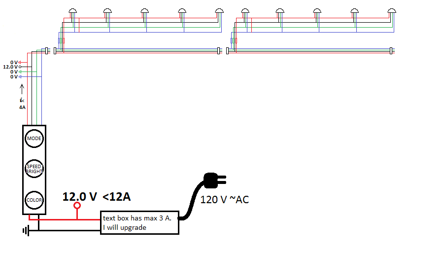
I was wondering if anyone could recommend an automatic voltage regulator (booster) for when I add/remove LEDs to a circuit in Parallel?
I currently have a 12v power source with 3A capability going into a 5 x 5mm RED LEDs.
As I add more LEDs (in segments of 5) I notice the lights begin to get dimmer and dimmer.
Is there a module of some sort that allows the voltage to be amplified as it drops to a certain point
Example: 5 Leds (1.8 Vf 20mA) are connected in parallel to 5 more Leds, then 5 more, then 5 more, then 5 more. Then the 3 added LED sets are removed leaving 2 sets of 5 LEDs. Is there a way to automatically increase/decrease voltage based upon the added sets?
A "parallel" example would be the adding and removing of christmas lights together.
Thank you in advance.
-Dats