Magfire 100

Rovert

Newly Enlightened
Joined
Sep 21, 2012
Messages
36
Location
Strailya
Hi Guys, I'm fairly new here & to flashlights also.
This is my first major mod, up until now i've only been doing minor stuff like led & driver swaps, de-doming, reflector swaps etc.
I am just a novice so please feel free to pull me up on anything i have said here that you feel is incorrect.
My name is Trevor & i'm an old guy that has spent my life modding/restoring/making stuff. I'm a house builder by trade which is my bread & butter but i also build & restore cars for some of my customers.
I have too many hobbies & along with that goes too many ex wives.
Enough about me onto this flashlight.
A while back I purchased a Trustfire X100 off Ali Express, it was pretty good for what it was.
Well made, generally good fit & finish, nice threads, good ano.
However, way, way under driven & for good reason.
The TF X100 appears to be a big chunk of Aluminium with really good potential via all of those radiating fins surrounding the head.
That is what appealed to me when I purchased it.
But all is not as it seems, read on.
I have seen a couple of guys mod this flashlight on various forums, but i feel they have failed to address the core problems with it.
Now this is just my take on this, maybe i haven't learned all i think i have in my time here.
Anyhow I'll let you guys form your own opinions, lets get some pics happening.

Above pic is what you see under the reflector of the TF X100, 7 X XML t6's.
The holes around the centre led are for screws to come up from under neath to hold the reflector down
 
Last edited:

Rovert

Newly Enlightened
Joined
Sep 21, 2012
Messages
36
Location
Strailya
Pretty Standard stuff, it really is a big chunky looking bit of gear.
But in reality the led's sit on a 3mm thick empty void.
I'll throw up a few more pics to show a bit more detail.

Above, Leds offf their stars

Above, stars removed from Head.
This shot shows the really crap job on the thermal epoxy.
it varied from really thick under some, to bearly half of the star stuck on others.

Above, Group parts shot

Above, This is where it gets interesting.
After inspecting the head I realised that the Led's sit on a 3mm thick platform with a large void underneath.
Here is the centre of the piece i removed.
The black dot in the centre is a divet filled with ano that was below the pass height of the milling process.
So, the centre led was left with a void filled with thermal adhesive under it, not real great for heat transfer.
If you look back at the third pic you will also see that the only way heat from the centre led can escape is via the small bit of ally between the reflector securing holes, which leads directly into the thermal path of the surrounding leds, poor effort.
 
Last edited:

Rovert

Newly Enlightened
Joined
Sep 21, 2012
Messages
36
Location
Strailya
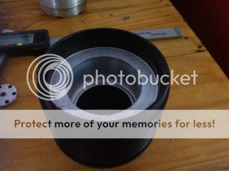
Here's a shot of the piece in the verniers for all to ponder.

I'll just go off for a moment so as to load a few more pics up to photobucket, whats with friggin photobucket lately anyway, it used to be so easy, now its just a big pita.
 

Rovert

Newly Enlightened
Joined
Sep 21, 2012
Messages
36
Location
Strailya
This is the void under the 3mm base, I have not enlarged it at all, just removed the ano off the sides as it was all coated.

Just a quick note, I dont have a Lathe or a Mill, all of the work seen here was done on a big old modified Taiwanese 15 speed drill press.
As you can see, simply replacing the driver with a higher power unit creates all sort of thermal issues.
The remaining ledge around the hole is not solid either, it is the top of the first layer of fins which is around 5mm thick.
In my opinion if you were just to mod the driver in this flashlight you would have a very short run time on high before thermal issues became apparent.
My goal with this light is to build something that puts out a massive amount of light that can be sustained for at least ten minutes on high, if not its a fail.
In Standard form the TF X100 reportedly puts out just over the 4000 lumens mark on high.
From 7 XML's in my opinion that is **** poor, but understandable.
My goal is to shoot for around 7000 lumens on high & sustainable as i said above for ten minites before thermal kickdown.
 
Last edited:

Rovert

Newly Enlightened
Joined
Sep 21, 2012
Messages
36
Location
Strailya
When I milled out the centre to remove the ano (i use the term "Mill" very loosely here) I made sure the extension piece that carries the driver & attaches the battery tube was in place & milled into it to remove the ano & get a flat surface

I always disliked the proportions of this light, particulary the long skinny handle.
It originally carries 4/26650's in series, combined with that big bulky head she was imo just butt ugly.
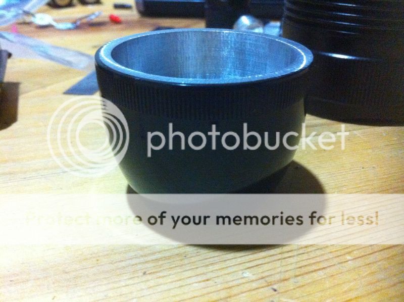
Next pic shows how i have modded the lower section to now take a Mag D Tube.

I Milled off the section that the stock handle screws into down to just above the driver battery contact boards position
Then cut the fins back to sit inside a bored & milled "D" Mag head.
 
Last edited:

Rovert

Newly Enlightened
Joined
Sep 21, 2012
Messages
36
Location
Strailya
The D mag head was then pressed onto the handle carrier with a bit of JB weld added for good measure.
Now back to the head.
I i turned down a piece of 6061 on the drill press to fit in the void.

I then pressed the two together this time with a slight smear of Arctic alumina 2 part thermal adhesive to take up any potential gaps.

As you can see the fit turned out okay, I then milled a smidge off the top to bring it all flush.
You can see the crap finish I get with the drill press here, it is completely flat but still needs to be smoothed out further.
It chatters like a ******* when i cut even at low cutting speeds & slow feed speed.
Flex is a biatch.
 
Last edited:

Rovert

Newly Enlightened
Joined
Sep 21, 2012
Messages
36
Location
Strailya
I have sinkpads on order from Las3r which i will mount XML2's onto.
I tossed up with keeping the original xml's for a while but i've come this far with it I might as well replace the emitters too.
I have Mil Spec Teflon wire on hand for the wiring & a 5 mode (no blinkys or flashys) KD 3amp driver to test out for suitability.
The driver input is stated as 6-12V but the also say its suitable for 2 or 3 li ions, either way I only intend on using 2 li ions mainly or 3 for a bit of extra runtime for an outing.
Batterys of choice for this build are Feilong 6000mah 32650's, i have used these in some of my other D cell Modded Mags & they are a great performer.
Plus I have spares on hand.
I have cut down a 3D Mag to 2D size for the battery tube & fitted a tail switch.
This now gives me the ability to use a standard Mag 1D extension tube for a third 32650 if I desire.

I really liked the look of the TF X100's Tail Cap, so got to thinking how I could incorporate it in the build
 
Last edited:

Rovert

Newly Enlightened
Joined
Sep 21, 2012
Messages
36
Location
Strailya
So this is what I did.
I turned down the outside of the TF Tailcap & bored the inside of the Mag D Cap


I then pressed them together with a smidge of JB Weld for good measure.
 
Last edited:

Rovert

Newly Enlightened
Joined
Sep 21, 2012
Messages
36
Location
Strailya
The switch in the TF tail cap was crap, so a new switch was in order.
I contacted VOB (Thanks again Matt) to see if he could help me out with a Judco 10amp switch, I have one of his 1D mags with a judco in the rear & its really good.
I had a Devil of a time trying to find a supplier in Aus for the Judco & Vob came to my assistance.
I really wanted to keep the TF's method to retain the switch which meant I now had to mod the Judco.
I cut the side of the casing off the judco & made new internal contact plates from some scrap copper sheet I have laying around.
The contacts now exit the switch on either side & are soldered to a contact plate which screws into the Tailcap.

I then turned down a plastic pipe fitting into a spacer & spring carrier & used a Mag "C" Tailcap spring.
 
Last edited:

Rovert

Newly Enlightened
Joined
Sep 21, 2012
Messages
36
Location
Strailya
Its wired through from the contact plate with 18awg Teflon wire to the base of the spring then solder braid directly from the contact plate to the top of the spring.
Should work okay me thinks.
And thats pretty much it for now.
I had pics of how i cut the Mag tube down but I cant find them, looks like I possibly deleted them.
You guys no how thats done anyway, plenty of tutorials here on CPF.
Finally a few pics of the light together in one piece.
Bear in mind I am waiting on sinkpads, so currently no led's installed.
The driver is in place & wires up to the Led position also.


Size comparison with a 2D Mag with FM Drop in adapter currently using a tripple XML2 drop in.


Rovert

Newly Enlightened
Joined
Sep 21, 2012
Messages
36
Location
Strailya
Thanks Mate, Dying to get the sinkpads so i can finish this sucker & post some results.
Dont think the driver i have will give me the output I am chasing.
Still looking at other options for it.
 
Top