The positive out from the driver is the same as the positive in. A single amc 7135 has three pins, they are
Neg In
Neg out
Positive In.
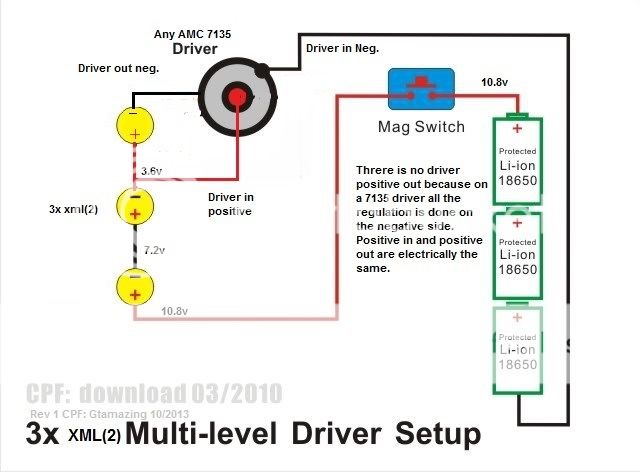
The current is regulated on the negative path from in to out. The positive is a control wire essentially turning the 7135 chip on or off.
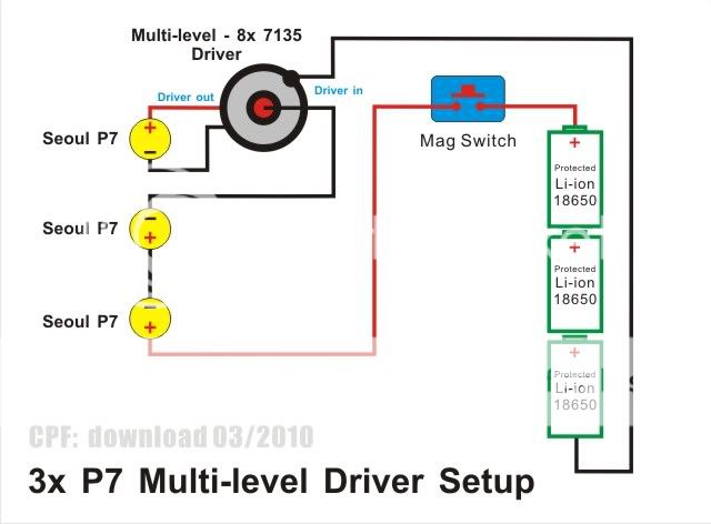
Now back too the circuit. Think of the circuit as a big loop ignoring the positive in to the driver. It looks like a big loop right? Lets say the voltage is a nominal 3.6v per cell x3= 10.8v total. Now you have 3 emitters in series. so each emitter see's 1/3 of the total voltage. That will be 3.6 volts. Now imagine the driver(7135 regulators) as a valve. That valve will control your current(3A). To open that valve you just need to add a positive to the driver. Amc 7135 based drivers have a max voltage of something like 4.5V so the positive for the driver is taken after the second led where it is 3.6v. The first led drops the volts to 7.2 the second drops it to 3.6 where you need it to be.
This circuit works best with equal amounts of led and batteries.